
Vertical ring high intensity magnetic separator and method for improving ore discharge efficiency of vertical ring high intensity magnetic separator

A strong magnetic separation and vertical ring technology, applied in the direction of high gradient magnetic separator, etc., can solve the problems of incomplete unloading and affecting the recovery of metal minerals

Pending Publication Date: 2017-12-15
LONGI MAGNET CO LTD
View PDF19 Cites 1 Cited by
  • Summary
  • Abstract
  • Description
  • Claims
  • Application Information

AI Technical Summary

Problems solved by technology

Since the media box adopts a specific structure of dislocation arrangement in the longitudinal direction, that is, from the outer diameter of the swivel to the inner diameter direction, the dielectric rods of each layer are arranged in a dislocation, resulting in incomplete ore unloading with a single upper outer side of the swivel. The ore unloading rate is in the range of 40-50%. Even with pressurized gas-water unloading, the ore unloading rate can only reach about 70%, which seriously affects the recovery of metal minerals

Method used


Image

  • Vertical ring high intensity magnetic separator and method for improving ore discharge efficiency of vertical ring high intensity magnetic separator
  • Vertical ring high intensity magnetic separator and method for improving ore discharge efficiency of vertical ring high intensity magnetic separator
  • Vertical ring high intensity magnetic separator and method for improving ore discharge efficiency of vertical ring high intensity magnetic separator

Examples


Embodiment Construction

[0018] The following will clearly and completely describe the technical solutions in the embodiments of the present invention with reference to the accompanying drawings in the embodiments of the present invention. Obviously, the described embodiments are only part of the embodiments of the present invention, not all of them. Based on the embodiments of the present invention, all other embodiments obtained by persons of ordinary skill in the art without making creative efforts belong to the protection scope of the present invention. Additionally, the protection scope of the present invention should not be limited only to the following specific structures or components or specific parameters.

[0019] The vertical ring strong magnetic separator provided by the present invention and the method for improving the unloading efficiency of the vertical ring strong magnetic separator are mainly based on the following principle: in the area above the horizontal line of the central axis ...


PUM


Abstract

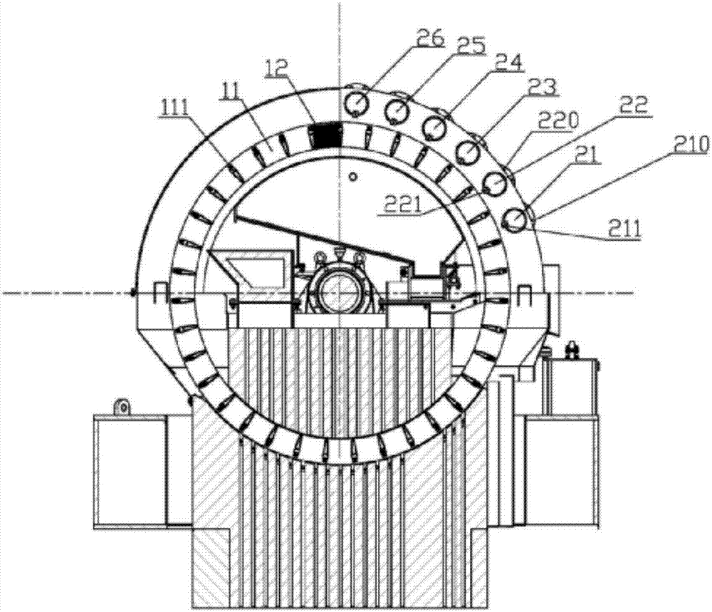
The invention discloses a vertical ring high intensity magnetic separator and a method for improving the ore discharge efficiency of the vertical ring high intensity magnetic separator. The method comprises the following step of sequentially arranging N (larger than or equal to 2) groups of air channels and water channels which are not connected with one another circumferentially in a region from the position above the medial axis horizontal line of a swivel to the perpendicular bisector of the diameter of the swivel. A material is repeatedly treated by N groups of a great quantity of high-pressure air and a small quantity of ore discharge water sequentially and alternately, so that the purpose of improving the ore discharge efficiency is realized. By adopting the vertical ring high intensity magnetic separator and the method, high-pressure air assistance is added for many times, and the dosage of the ore discharge water is lowered on the basis of increasing the ore discharge pressure and keeping the ore discharge effect unchanged, so that the concentration of high-concentration ores cannot be lowered, the working efficiency of subsequent ore dressing is improved, waste of water resources is also reduced, the ore discharge efficiency is effectively improved by 20 percent or above at the same time, the ore dressing handing capacity is promoted to be remarkably increased, and the service life of equipment is prolonged.

Description

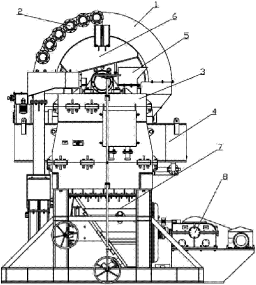
technical field [0001] The invention belongs to the technical field of magnetic separation, and in particular relates to a vertical ring strong magnetic separator and a method for improving ore unloading efficiency. Background technique [0002] At present, domestic vertical ring strong magnetic separation equipment is also called vertical ring high gradient magnetic separator. Its main structure and working principle is that the ring body rotates vertically. Through the amplification of the yoke, a large background field strength is formed in the central area of ​​the coil. , when the induction medium box in the swivel passes through this area, a higher field strength is induced, but when the material passes through the induction medium box in this area, the magnetic material in the slurry is absorbed by the induction medium rod, and leaves the magnetic field with the rotation of the swivel ring In the area, an ore unloading device is installed on the upper part of the oute...

Claims


Application Information

Patent Timeline
IPC IPC(8): B03C1/025B03C1/031B03C1/033
CPCB03C1/025B03C1/031B03C1/033
Inventor 张承臣马越刘振凯
Owner LONGI MAGNET CO LTD
Learn More