Automatic screw driving device

An automatic locking and automatic locking technology, which is applied in metal processing, metal processing equipment, manufacturing tools, etc., can solve the problems of uncontrollable downforce, high labor cost, inaccurate locking, etc., to overcome uncontrollable pressure and solve the problem of The effect of low production efficiency and high-efficiency conveying method

Pending Publication Date: 2017-12-15
上海莘翔自动化科技有限公司
View PDF0 Cites 7 Cited by
  • Summary
  • Abstract
  • Description
  • Claims
  • Application Information

AI Technical Summary

Problems solved by technology

[0003] At present, the vast majority of assembly operations still use the method of manually locking screws. This method is more suitable for small batch production processes, but for large batch production processes, there will be disadvantages of low production efficiency and high labor costs.
Manual locking of screws also has certain requirements for operators. Inexperience will result in inaccurate locking, and the consistency of locking torque of each screw cannot be guaranteed. If the torque is too small, the screws will easily loosen, reducing the The reliability of the entire assembly work, the torque is too large, it is easy to slip t

Method used


Image

  • Automatic screw driving device
  • Automatic screw driving device
  • Automatic screw driving device

Examples


Example Embodiment

[0024] The technical solutions in the embodiments of the present invention will be clearly and completely described below in conjunction with the accompanying drawings in the embodiments of the present invention. Obviously, the described embodiments are only a part of the embodiments of the present invention, rather than all the embodiments. Based on the embodiments of the present invention, all other embodiments obtained by those of ordinary skill in the art without creative work shall fall within the protection scope of the present invention.
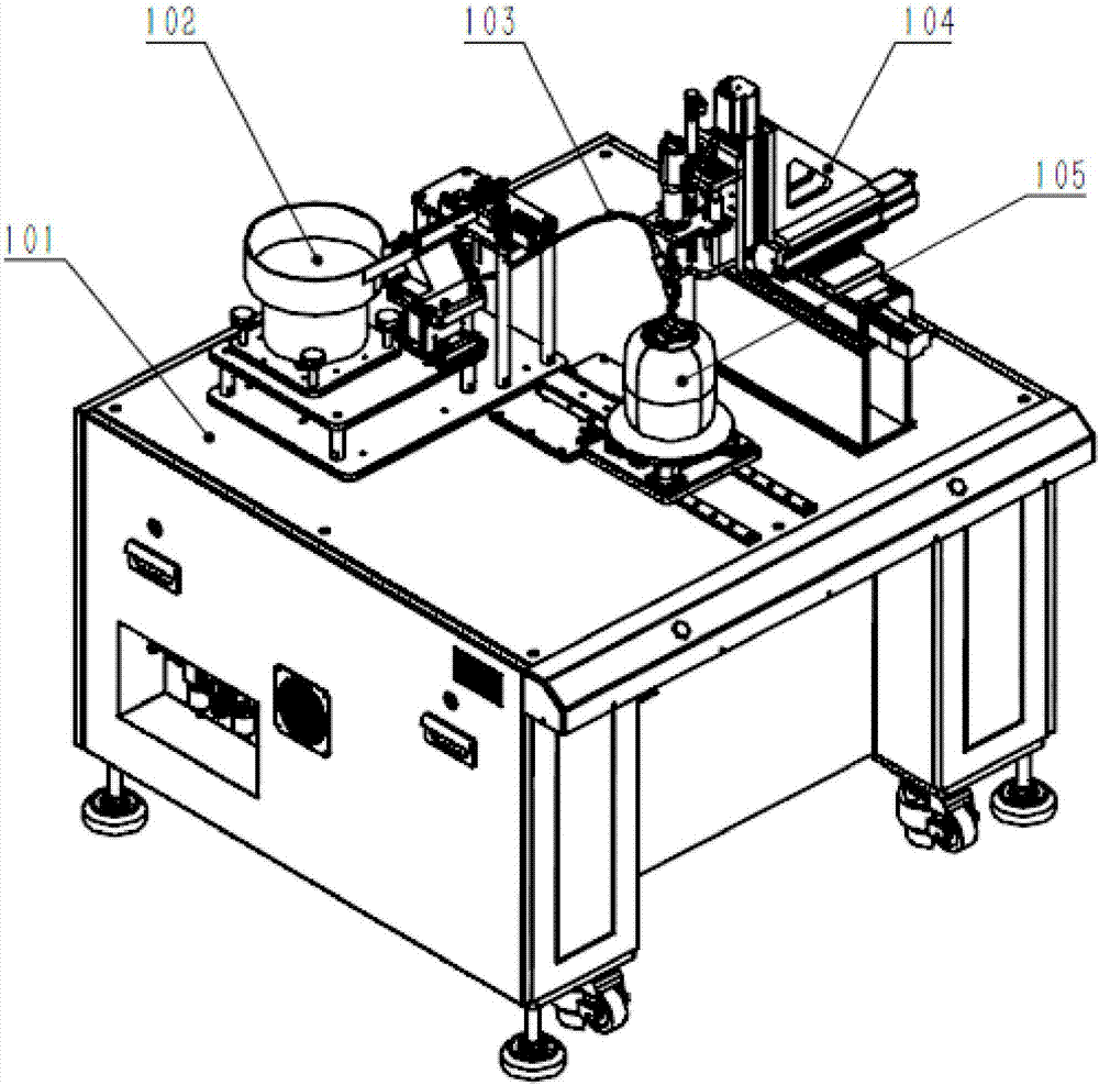
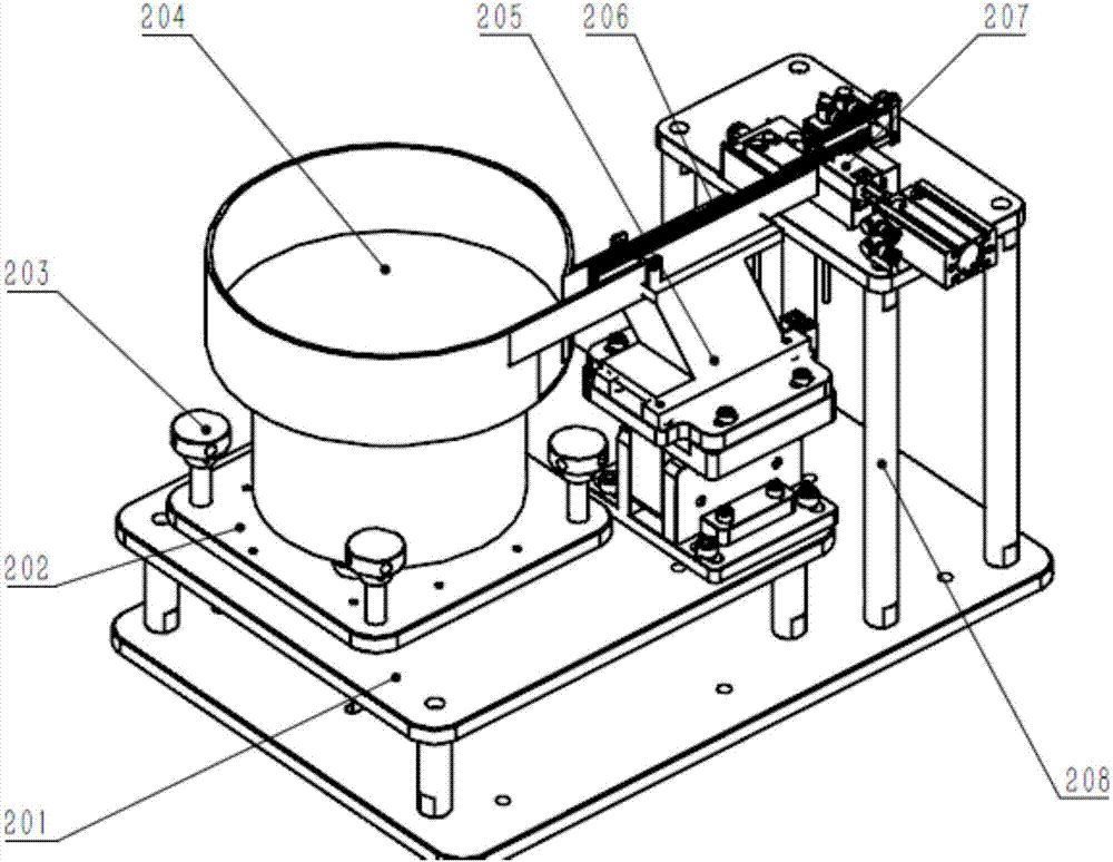
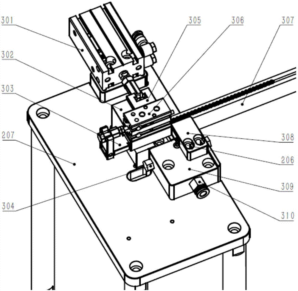
[0025] See Figure 1 to Figure 7 , An automatic locking device, the workbench 101 is provided with a screw automatic feeding mechanism 102 and a screw guide tube 103, an automatic locking mechanism 104 and a workpiece feeding mechanism 105, and a screw automatic feeding mechanism 102, an automatic locking mechanism 104 and a workpiece The feeding mechanism 105 is fixed on the workbench 101 by screws. A screw guide tube 103 is connected ...


PUM


Abstract

The invention discloses an automatic locking device. The working table is provided with a screw automatic feeding mechanism, a screw guide tube, an automatic locking mechanism and a workpiece feeding mechanism, and the screw automatic feeding mechanism, the automatic locking mechanism and the workpiece feeding mechanism pass through the screw Fixed on the workbench. A screw feed pipe is connected between the screw automatic feeding mechanism and the automatic locking mechanism, and the vibrating plate of the screw feeding mechanism is fixed on the vibrating plate mounting plate by screws. The manual locking screw method has the problems of low production efficiency, high labor cost, inaccurate locking, easy loosening of screws caused by too small locking torque or slipping teeth caused by excessive torque, and it also overcomes the problems of existing locks on the market. The screw machine has the disadvantages of uncontrollable pressure during locking, low safety and low degree of automation.

Description

technical field [0001] The invention relates to the technical field of mechanical manufacturing, in particular to an automatic locking device. Background technique [0002] Locking screws is the most basic and common assembly task in assembly manufacturing. [0003] At present, the vast majority of assembly operations still use the method of manually locking screws. This method is more suitable for small batch production processes, but for large batch production processes, there will be disadvantages of low production efficiency and high labor costs. Manual locking of screws also has certain requirements for operators. Inexperience will result in inaccurate locking, and the consistency of locking torque of each screw cannot be guaranteed. If the torque is too small, the screws will easily loosen, reducing the The reliability of the entire assembly work, the torque is too large, it is easy to slip the teeth, resulting in damage to the threaded holes of the assembled parts an...

Claims


Application Information

Patent Timeline
IPC IPC(8): B23P19/06
CPCB23P19/001B23P19/004B23P19/06
Inventor 吕军辉朱文娟徐田庚
Owner 上海莘翔自动化科技有限公司
Why Eureka
Try Eureka