
Power panel for robot and robot
A technology of robots and power boards, applied to instruments, simulators, manipulators, etc., can solve the problems of fixed functions, few functions, and the inability to develop and upgrade chips, and achieve reliable control and small size.
Patent Information
- Authority / Receiving Office
- CN · China
- Patent Type
- Applications(China)
- Current Assignee / Owner
- Publication Date
- 2017-12-15
- Estimated Expiration
- Not applicable · inactive patent
Smart Images
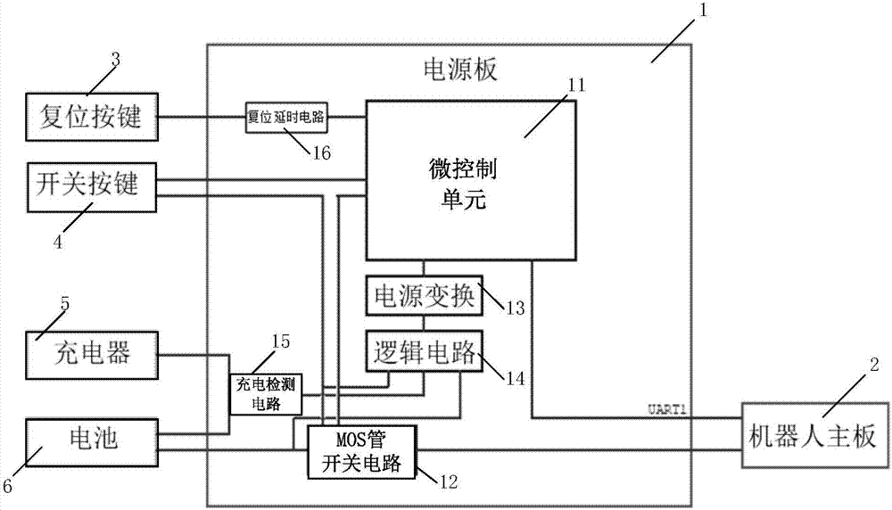
Figure 1 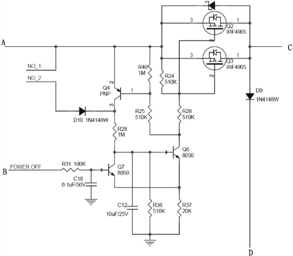
Figure 2
Abstract
Description
technical field
[0001] The invention relates to the technical field of robot power control, in particular to a power board for a robot and a robot. Background technique
[0002] In recent years, with the development of artificial intelligence technology, the use of various robots has become more and more common. In life and work, robots with different functions can help people complete part of their work. For example, sweeping robots can help people clean their houses, and restaurant robots can assist waiters in delivering food to customers.
[0003] In the prior art, the robot can use a mechanical switch (for example, a ship-type switch), but its disadvantage is that it needs to be turned off manually, which is inconvenient to operate. The robot can also use a dedicated chip similar to a laptop computer to control the opening and closing of the power supply circuit system, but this type of dedicated chip has fewer functions and fixed functions. For a robot, the different ...
Examples
Embodiment Construction
[0020] In order to make the above objects, features and advantages of the present invention more comprehensible, specific implementations of the present invention will be described in detail below in conjunction with the accompanying drawings.
[0021] Such as figure 1 What is shown is a schematic diagram of a power board for a robot according to an embodiment of the present invention.
[0022] refer to figure 1 , The power board 1 includes a micro control unit 11 , a MOS transistor switch circuit 12 , a power converter 13 , a logic circuit 14 , a charging detection circuit 15 and a reset delay circuit 16 .
[0023] A switch button interface (not shown) is provided on the micro control unit 11 for connecting the switch button 4 . When the micro control unit 11 detects that the switch button 4 is pressed, the battery 6 supplies power to the power board 1, and turns on the power circuit system of the robot. The power conversion 13 provides power for the micro control unit 11 ...