
A high-efficiency vacuum pumping mechanism for a vulcanizing machine

A technology for vacuuming and vulcanizing machines, which is applied in the field of high-efficiency vacuuming mechanisms, which can solve the problems of large invalid space occupation, prolonged production time, and large occupied space, and achieve the effects of reducing vacuuming space, improving quality, and increasing speed

Active Publication Date: 2019-07-09
DONGYUNINGBOHYDRAULIC MACHINE INDAL
View PDF3 Cites 0 Cited by
  • Summary
  • Abstract
  • Description
  • Claims
  • Application Information

AI Technical Summary

Problems solved by technology

Make the production time of the product longer and affect the production efficiency of the product
Moreover, this mechanism has a disadvantage that it takes up a lot of space. The larger the machine panel, the larger the invalid space is, and the slower the vacuuming rate is.
In addition, the vulcanization time of rubber products should not be too long. If the time is too long, it will cause overvulcanization and even cause the products to be scrapped.

Method used


Image

  • A high-efficiency vacuum pumping mechanism for a vulcanizing machine
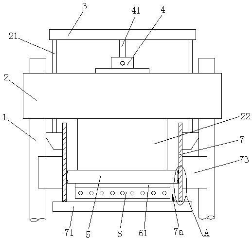
  • A high-efficiency vacuum pumping mechanism for a vulcanizing machine
  • A high-efficiency vacuum pumping mechanism for a vulcanizing machine

Examples


Embodiment Construction

[0022] The present invention will be further described in detail below in conjunction with the accompanying drawings and embodiments.

[0023] Such as Figure 1 to Figure 3 Shown is the structural representation of the present invention,

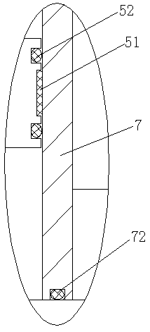
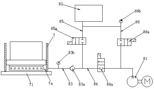
[0024] The reference signs are: pillar 1, top seat 2, coupling column 21, fixed seat 22, fixed plate 3, vacuum cover oil cylinder 4, piston rod 41, piston plate 5, wear-resistant sheet 51, first sealing strip 52, Hot plate 6, heat insulation plate 61, vacuum cover frame 7, vacuum chamber 7a, slide plate 71, second sealing strip 72, copper lining seat 73, vacuum pump 81, vacuum storage barrel 82, vacuum main pipe 83, check valve 83a, Main pipe vacuum gauge 83b, first branch pipe 84, first electromagnetic switch 84a, second branch pipe 85, second electromagnetic switch 85a, third branch pipe 86, third electromagnetic switch 86a, branch pipe vacuum gauge 86b.

[0025] Such as Figure 1 to Figure 3 as shown,

[0026] A high-efficiency vacuum...


PUM


Abstract

Disclosed is an efficient vacuum pumping mechanism of a vulcanizing machine. The efficient vacuum pumping mechanism of the vulcanizing machine comprises a top base, wherein the top base is assembled on supporting columns. Connecting columns are arranged on the top base in a penetrating mode, and a fixed plate is fixedly arranged at the upper ends of the connecting columns. A vacuum cover oil cylinder is arranged above the top base, and the upper end of a piston rod of the vacuum cover oil cylinder is fixedly connected with the top base. A fixed base is arranged at the bottom of the top base, and a piston plate is arranged at the lower end of the fixed base. A heating disc is fixedly arranged on the piston plate, and a vacuum cover frame is arranged below the top base. A sliding plate is arranged at the bottom of the vacuum cover frame, the lower ends of the connecting columns are connected with the vacuum cover frame, and the periphery of the piston plate and the vacuum cover frame are in sealing fit. When the vacuum cover frame descends and is combined with the sliding plate to achieve die assembly, a vacuum chamber is formed in the vacuum cover frame and located between the piston plate and the sliding plate, and the heating disc is located in the vacuum chamber. The vacuum chamber is connected with a vacuum pumping circuit, and the vacuum pumping circuit mainly comprises a vacuum pump and a vacuum storage barrel, wherein the vacuum chamber and the vacuum storage barrel can conduct air convection. The efficient vacuum pumping mechanism of the vulcanizing machine has the advantages that the structure is simple, and the vacuum pumping efficiency can be effectively improved.

Description

technical field [0001] The invention relates to the technical field of vulcanizing machine manufacturing, in particular to a high-efficiency vacuuming mechanism for a vulcanizing machine. Background technique [0002] Generally, the vulcanizing machine is equipped with an upper hot plate and a lower hot plate. During processing, the rubber material is injected into the mold. When the mold moves between the upper hot plate and the lower hot plate, the upper hot plate and the lower hot plate clamp the mold and use The heat generated by the upper heating plate and the lower heating plate heats the rubber material in the mold to melt and form the rubber material. [0003] Now, due to the continuous development of model rubber products, conveyor belts, rubber sheets and synthetic materials, it not only promotes the improvement of the overall level of the flat vulcanizing machine, but also greatly improves its structure. In order to achieve the high quality of rubber products, a ...

Claims


Application Information

Patent Timeline
Patent Type & Authority Patents(China)
IPC IPC(8): B29C35/02
CPCB29C35/0238
Inventor 杨桢堂舒浩梅沈健林开文纪雪芳
Owner DONGYUNINGBOHYDRAULIC MACHINE INDAL
Learn More