3D printing method for printing colorful models

A 3D printing and model technology, applied in the field of 3D printing, can solve the problems of a single color matching form, a large amount of calculation, and a small amount of resources, and achieve the effect of a simple coloring process.

Active Publication Date: 2017-12-15
QINGDAO R & D INST XIAN JIAOTONG UNIV
View PDF5 Cites 8 Cited by
  • Summary
  • Abstract
  • Description
  • Claims
  • Application Information

AI Technical Summary

Problems solved by technology

However, this method is costly, requires high technical requirements, and has a large amount of computation, making it difficult to popularize.
[0007] Summarize the above three methods, which include the following problems: difficult modeling, less resources, poor molding quality, single color matching form, difficult to promote, etc.

Method used


Image

  • 3D printing method for printing colorful models
  • 3D printing method for printing colorful models
  • 3D printing method for printing colorful models

Examples


Embodiment 1

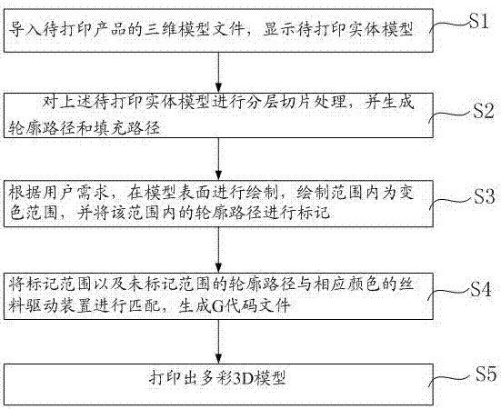
[0046] S1, importing the Stl file into the software to display the solid model;

[0047] S2, in the Z-axis direction, slice the solid model, each unit height is one slice, and finally transform the complete solid into an approximate solid stacked by many thin slices, and mark the outline, filling, top surface and bottom surface of each layered slice and other feature information to generate contour paths and fill paths; determine whether support surfaces need to be added, and if so, generate support paths based on the support areas that need to be added.

[0048] In this embodiment, judging whether to add a support surface is realized through the following steps: project the model to the bottom surface, filter out the overhang surface, calculate the inclination angle and span length of each surface, and mark it as a support surface if it exceeds the set critical value.

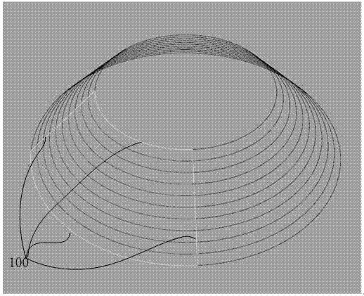
[0049] S3, draw on the surface of the model according to the user's needs, the range of color change is withi...

Embodiment 2

[0075] The drawing process in step S3 and the process of marking the outline path with color will be described below.

[0076] Drawing method one:

[0077] The mouse pointer turns into a round brush (similar to the paintbrush of drawing software, the diameter of the brush can be set) to paint on the surface of the model, and the covered path is marked with color. The color of the brush can be set, and it can be painted multiple times. The last time prevails, the same color part integrates a complete area, and the intersection of the boundary line of the complete area and the model outline path is used as a color-changing node.

[0078] When filtering the intersection point, after multiple times of coloring, the generated nodes inside the same color area will be deleted; the color boundary line is tangent to the model outline path line, an intersection point will be generated, and it will be deleted.

[0079] drawing method two,

[0080] The paintbrush is a point, draws a lin...

Embodiment 3

[0081] Embodiment 3, illustrate with two kinds of color silk material replacement processes below

[0082] E1 is a wire feeding device for conveying white silk, and E2 is a wire feeding device for conveying black silk;

[0083] E1 0 E2 0 (initial, the value of each extrusion head is 0)

[0084] E1 0.56 E2 0 (E1 changes from 0 to 0.56mm, that is, the filament is extruded from E1; if the value of E2 remains unchanged, there is no extrusion action).

[0085] E1 0.56E2 0.23 (the value of E1 remains unchanged, E1 is not extruded; E2 is changed from 0 to 0.23, that is, the length of 0.23 is extruded from E2).


PUM


Abstract

The invention provides a 3D printing method for printing colorful models. The 3D printing method comprises the following steps: (S1) three-dimensional model files of products to be printed are leaded in; and solid models to be printed are displayed; (S2) the layered slicing is performed on the solid models to be printed to generate profile paths and filling paths; (S3) the surfaces of the models are drawn according to user demands; color change ranges are in the drawing ranges; and the profile paths in the ranges are marked; (S4) the profile paths in the marked ranges and the non-marked ranges are matched with wire driving devices with corresponding colors to generate G code files; and (S5) colorful 3D models are printed. The 3D printing method is simple in the coloring treatment process of the models, needs no special processing for the files, and is suitable for conventional STL model files.

Description

technical field [0001] The invention belongs to the technical field of 3D printing, in particular to a 3D printing method for printing colorful models. Background technique [0002] The technical principle of 3D printing is to slice the 3D model layer by layer, formulate the printing trajectory according to the contour information of each layer, and accumulate and shape from bottom to top. [0003] At present, if you want to print a multi-color 3D model, you can generally achieve it through the following three methods: [0004] (1) Multiple single-color extrusion heads need to be composed of multiple wire feeding systems. Each extrusion head is equipped with a specific color of wire. At least two complementary model files are required for printing. The color 1 part is saved as an entity , the color 2 part is saved as an entity. When slicing, different entities are sliced ​​separately to generate two sets of path codes. When printing, the code path generated by the color 1 e...

Claims


Application Information

Patent Timeline
Patent Type & Authority Applications(China)
IPC IPC(8): B29C64/118B29C64/30B29C64/386G06F3/12B33Y30/00B33Y50/00
CPCB33Y30/00B33Y50/00G06F3/1203
Inventor 李耀鹏张建勋李增辉毕利君
Owner QINGDAO R & D INST XIAN JIAOTONG UNIV
Why Eureka
Try Eureka