
Turning mechanism for large-diameter main mirror

A flipping mechanism and large-diameter technology, applied in the field of optical instruments, can solve the problems of the main mirror's external size, weight increase, axial support force and radial support force changes, high cost, etc., and achieve a simple and fast flip process, support area Reduced, high utility value effects

Inactive Publication Date: 2017-12-15
CHANGCHUN INST OF OPTICS FINE MECHANICS & PHYSICS CHINESE ACAD OF SCI
View PDF3 Cites 0 Cited by
  • Summary
  • Abstract
  • Description
  • Claims
  • Application Information

AI Technical Summary

Problems solved by technology

[0002] In the technical fields of space detection and astronomical observation, in order to improve the resolution, it is necessary to increase the aperture of the photoelectric detection equipment, resulting in a sharp increase in the size and weight of the primary mirror, and the cost is very expensive
[0003] Due to the fragility and fragility of the material of the primary mirror, certain risks are associated with its lifting, flipping, and transporting operations. Especially during the flipping process of the primary mirror, the axial support force and radial The supporting force changes, and the position of the primary mirror will shift along the direction of gravity, and there is a huge risk in the process
If the local stress is too large during the flipping process, the primary mirror may be irreversibly damaged such as chipping, shattering, and fracture, which will bring a great delay to the development and service life of the entire photoelectric detection equipment and a sharp increase in cost

Method used


Image

  • Turning mechanism for large-diameter main mirror
  • Turning mechanism for large-diameter main mirror
  • Turning mechanism for large-diameter main mirror

Examples


Embodiment Construction

[0053] The following will clearly and completely describe the technical solutions in the embodiments of the present invention with reference to the accompanying drawings in the embodiments of the present invention. Obviously, the described embodiments are only some, not all, embodiments of the present invention. Based on the embodiments of the present invention, all other embodiments obtained by persons of ordinary skill in the art without making creative efforts belong to the protection scope of the present invention.

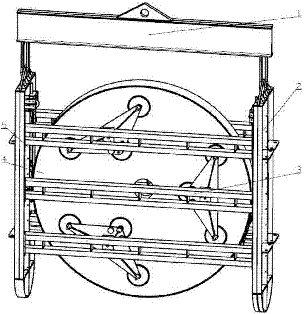
[0054] The core improvement of the large-caliber primary mirror flip mechanism provided by the embodiment of the present invention is that it includes a lifting beam assembly 1, a frame assembly 2, an axial support assembly 3 and a radial support assembly 5, such as figure 1 shown;

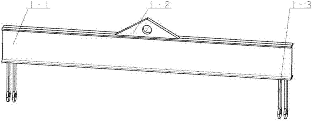
[0055] Wherein, the frame assembly 2 is installed on the lower part of the lifting beam assembly 1; the function of the lifting beam assembly 1 is to realize connection with the f...


PUM


Abstract

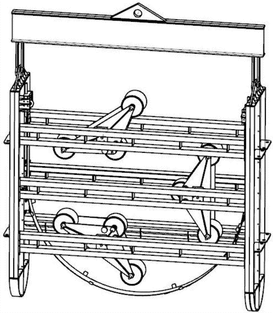
The invention discloses a turning mechanism for a large-diameter main mirror. A hoisting beam assembly of the turning mechanism evenly disperses one-point hoisting concentrated force into two identical degrees of small dispersed hoisting force, and thus the whole turning mechanism is kept balanced. A frame assembly serves as a supporting framework of the whole turning structure, and round pieces at the bottom of the frame assembly are used for making contact with the ground in the turning process, so that a smooth turning process and small vibration are ensured, and extra stress is prevented from being introduced. Two axial supporting assemblies are placed on the back side and the front side of the main mirror correspondingly and used for unloading axial force of the main mirror, and three-point supporting force is dispersed into nine parts of dispersed supporting force according to the Whiffle-tree principle, so that uniform release of the supporting force is fully achieved, and it is ensured that risks caused by stress concentration of the back side and the front side of the main mirror are avoided. A radial supporting assembly makes full contact with half of the circumference of the main mirror through a large flexible steel sheet, local supporting force of the main mirror is reduced by enlarging the contact area, and thus the safety of the main mirror in the turning process is ensured.

Description

technical field [0001] The invention relates to the technical field of optical instruments, in particular to a large-caliber primary mirror turning mechanism. Background technique [0002] In the technical fields of space detection and astronomical observation, in order to improve the resolution, it is necessary to increase the aperture of the photoelectric detection equipment, resulting in a sharp increase in the size and weight of the primary mirror, and the cost is very expensive. [0003] Due to the fragility and fragility of the material of the primary mirror, certain risks are associated with its lifting, flipping, and transporting operations. Especially during the flipping process of the primary mirror, the axial support force and radial The supporting force changes, and the position of the primary mirror will shift along the direction of gravity, and there is a huge risk in the process. If the local stress is too large during the flipping process, the primary mirror...

Claims


Application Information

Patent Timeline
Patent Type & Authority Applications(China)
IPC IPC(8): B66C1/10B66C13/08
CPCB66C1/10B66C13/08
Inventor 孙敬伟吴小霞王建立赵金宇
Owner CHANGCHUN INST OF OPTICS FINE MECHANICS & PHYSICS CHINESE ACAD OF SCI
Learn More