A combustion device for injecting ammonia in the center of the burner for industrial pulverized coal boilers
A pulverized coal boiler and combustion device technology, which is applied to the burner, burner, and combustion type of powdered fuel, can solve the problems of poor load change adjustment ability, high NOx emission reduction cost, and high NOx emission. The effect of contacting, alleviating slagging phenomenon in the furnace, and reducing NOx content
- Summary
- Abstract
- Description
- Claims
- Application Information
AI Technical Summary
Problems solved by technology
Method used
Image
Examples
specific Embodiment approach 1
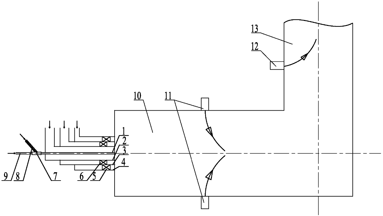
[0022] Specific implementation mode one: combine figure 1 and figure 2 Describe this embodiment, a combustion device for injecting ammonia in the center of the burner for an industrial pulverized coal boiler in this embodiment includes a primary air duct 1, a direct current secondary air duct 2, a secondary air duct 3 in a swirling flow, Secondary air pipe 4 outside the swirling flow, mixer 7, amino reducing agent conveying pipe 8, concentrated pulverized coal conveying pipe 9, furnace 10 and two-stage burn-off air system, primary air pipe 1, DC secondary air pipe 2, cyclone The secondary air pipe 3 inside the flow and the secondary air pipe 4 outside the swirling flow are arranged sequentially from the inside to the outside, the amino reducing agent delivery pipe 8 and the concentrated pulverized coal delivery pipe 9 are respectively connected to the inlet end of the mixer 7, and the outlet of the mixer 7 The outlet end is connected to the inlet end of primary air duct 1, a...
specific Embodiment approach 2
[0023] Specific implementation mode two: combination figure 1This embodiment is described. The primary air duct 1 , the DC secondary air duct 2 , the secondary air duct 3 inside the swirl flow, and the secondary air duct 4 outside the swirl flow described in this embodiment are arranged coaxially. The undisclosed technical features in this embodiment are the same as those in the first embodiment.
specific Embodiment approach 3
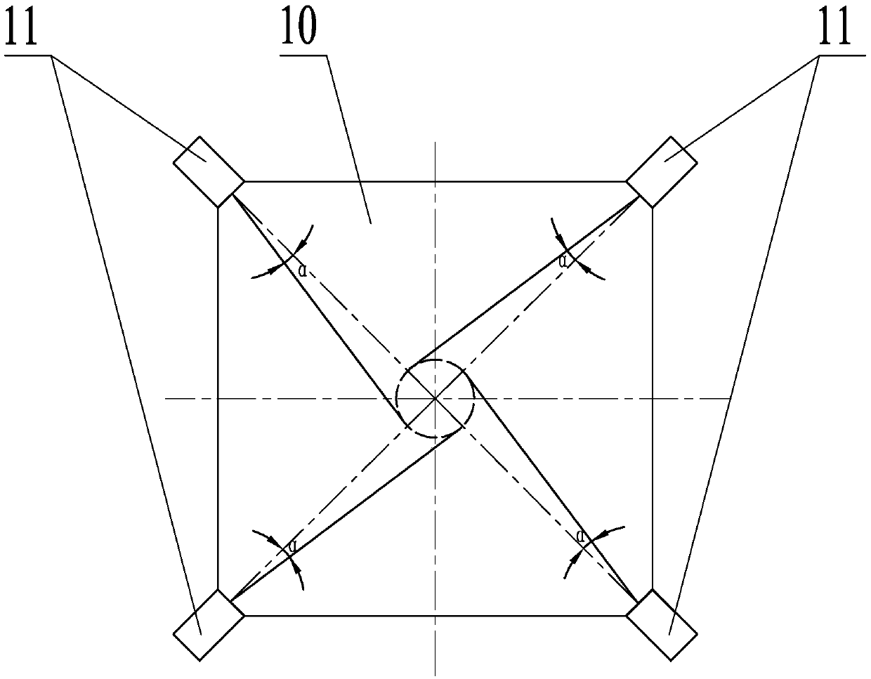
[0024] Specific implementation mode three: combination figure 1 and figure 2 Describe this embodiment. The two-stage overfire air system in this embodiment includes multiple primary overfire air nozzles 11 and multiple secondary overfire air nozzles 12. The vertical circumferential direction of each primary overburning air nozzle 11 is set at an angle α between the injection direction and the center of the furnace 10, and the secondary overburning air nozzle 12 is arranged on the upward flue 13 of the furnace 10 On the front wall, multiple secondary burn-off air nozzles 12 are evenly distributed along the horizontal circumferential direction of the upward flue 13 . The undisclosed technical features in this embodiment are the same as those in the first or second specific embodiment.
[0025] The injection direction of each primary overburning air spout 11 forms an inclination angle with the center of the furnace 10, so that the four jets sent into the furnace 10 from the pr...
PUM
 Abstract
Description
Claims
Application Information
 - R&D
- Intellectual Property
- Life Sciences
- Materials
- Tech Scout
- Unparalleled Data Quality
- Higher Quality Content
- 60% Fewer Hallucinations
Browse by: Latest US Patents, China's latest patents, Technical Efficacy Thesaurus, Application Domain, Technology Topic, Popular Technical Reports.
© 2025 PatSnap. All rights reserved.Legal|Privacy policy|Modern Slavery Act Transparency Statement|Sitemap|About US| Contact US: help@patsnap.com


