
Multi-light-source single-liquid-crystal projection illumination system

A liquid crystal projection and lighting system technology, applied in optics, instruments, projection devices, etc., can solve the problems of low light source utilization and high light source power requirements, and achieve the effects of improving uniformity, utilization, and image quality.

Pending Publication Date: 2017-12-15
CHENGDU JIUTIAN HUAXIN TECH CO LTD
View PDF7 Cites 5 Cited by
  • Summary
  • Abstract
  • Description
  • Claims
  • Application Information

AI Technical Summary

Problems solved by technology

[0008] The present invention overcomes the deficiencies of the prior art, provides a multi-light source single liquid crystal projection lighting system with high light source utilization rate, and solves the problems of low light source utilization rate and high light source power requirement in the existing liquid crystal screen lighting system

Method used


Image

  • Multi-light-source single-liquid-crystal projection illumination system

Examples


Embodiment 1

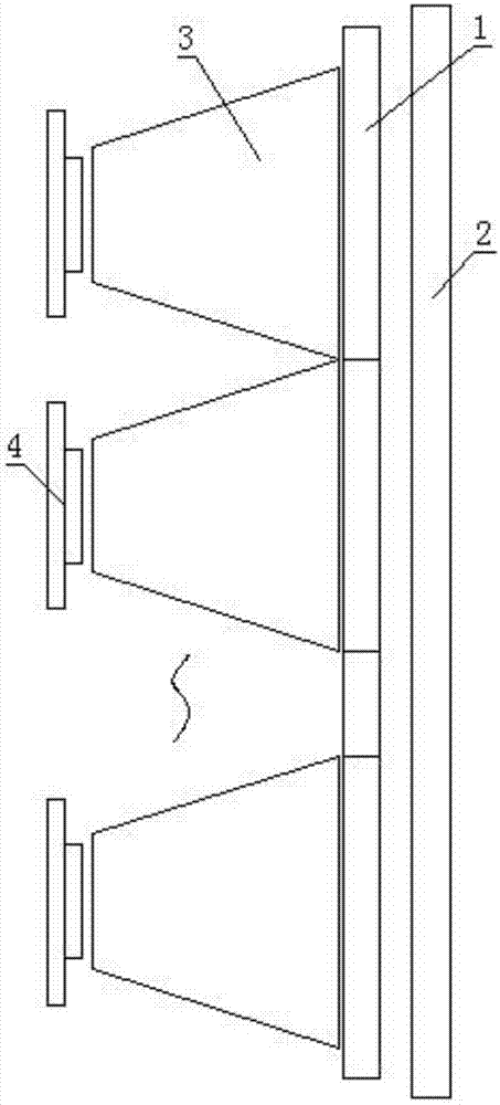
[0030] Such as figure 1 As shown, the present invention comprises a Fresnel lens 1, and the Fresnel lens 1 is arranged behind the liquid crystal screen 2, and the side of the Fresnel lens 1 away from the liquid crystal screen 2 is provided with several light source assemblies, and the light source assembly includes a uniform light device 3 and The light source 4 and the uniform light device 3 are arranged on the side of the Fresnel lens 1 away from the liquid crystal screen 2, and the light source 4 is arranged on the side of the uniform light device 3 away from the Fresnel lens 1; the light emitted by the light source 4 passes through the uniform light device 3 After being reflected or refracted, it is incident on the Fresnel lens 1 in a quasi-vertical direction, and the light passing through the Fresnel lens 1 is irradiated onto the liquid crystal screen 4 .

[0031] The present invention has a plurality of light source assemblies, and the light rays emitted by the plurality...

Embodiment 2

[0034] On the basis of the first embodiment, the light-gathering surface of the light homogenizing device 3 is one of a total reflection surface or a curved surface of a refracting lens.

[0035] The uniform light device 3 changes the light emitted by the light source 4 to be roughly parallel to each other through reflection or transmission, so that all the light is incident on the Fresnel lens 1 in a direction perpendicular to the Fresnel lens 1, so that the light is finally evenly incident on the LCD screen 2. When the light is uniformly incident, the power requirement of the light source 4 can be relatively low, which improves the utilization rate of the light source 4 itself.

Embodiment 3

[0037] On the basis of Embodiment 1 or Embodiment 2, the light-gathering surface of the light-homogenizing device 3 is a total reflection surface, and the shape of the light-gathering surface of the light-homogenizing device 3 has integral characteristics or is a free-form surface. The shape of the homogenizing device 3 can be a trapezoidal conical shape.

[0038] When the shape of the light-gathering surface of the homogenizing device 3 has integral characteristics or is a free-form surface, the homogenizing device 3 reflects the light emitted by the light source 4, and the reflected light can be incident on the Fresnel lens 1 in a direction parallel to each other.


PUM


Abstract

The invention relates to the field of liquid crystal projection, and especially relates to a multi-light-source single-liquid-crystal projection illumination system. The technical scheme of the invention is that the system comprises a Fresnel lens; the Fresnel lens is disposed behind a liquid crystal screen; one side, far from the liquid crystal screen, of the Fresnel lens is provided with a plurality of light source modules; each light source module comprises a light equalizing device and a light source, wherein the light equalizing device is disposed at one side, far from the liquid crystal screen, of the Fresnel lens, and the light is disposed at one side, far from the Fresnel lens, of the light equalizing device; the light emitted by the light sources is reflected or refracted by the light equalizing devices, and then enters the Fresnel lens in a quasi-vertical direction; the light passing through the Fresnel lens irradiates the liquid crystal screen. The system provided by the invention solves problems that a conventional liquid crystal screen illumination system is low in utilization rate of light sources, and is high in requirements for the power of the light sources.

Description

technical field [0001] The invention relates to the field of liquid crystal projection, in particular to a single liquid crystal projection lighting system with multiple light sources. Background technique [0002] Today's projection device products are very diverse. For example, digital light processing projection devices, liquid crystal projection devices, and reflective single crystal silicon projection devices are all provided to different consumer groups. Taking the digital light processing projection device that is common on the market at present as an example, the DLP projection device is based on the micro-electromechanical system technology, and uses the DMD chip developed by Texas Instruments to form the main structure of the projection device. At present, the common multimedia projection systems on the market can be divided into two types according to the light sources used: projection systems using high-efficiency light bulbs and projection systems using LED ligh...

Claims


Application Information

Patent Timeline
Patent Type & Authority Applications(China)
IPC IPC(8): G03B21/20
CPCG03B21/2026G03B21/2033G03B21/208
Inventor 张锦
Owner CHENGDU JIUTIAN HUAXIN TECH CO LTD
Learn More