

Modulation device for fixing solution of imaging department
A fixer and image technology, applied in photography, photography technology, optics, etc., can solve the problems of inconvenient control of stirring force, time-consuming and labor-intensive, and affecting the modulation effect, etc.
- Summary
- Abstract
- Description
- Claims
- Application Information
AI Technical Summary
Problems solved by technology
Method used
Image

Examples
Embodiment 1
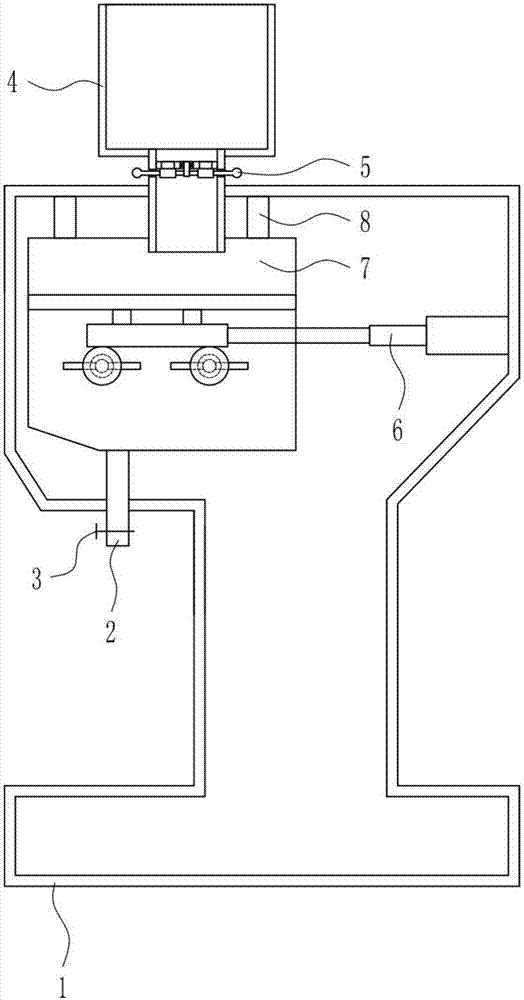
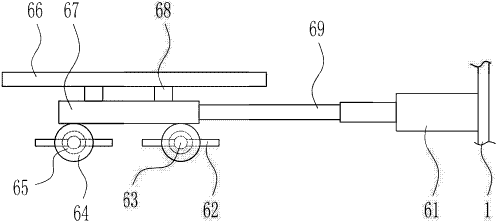
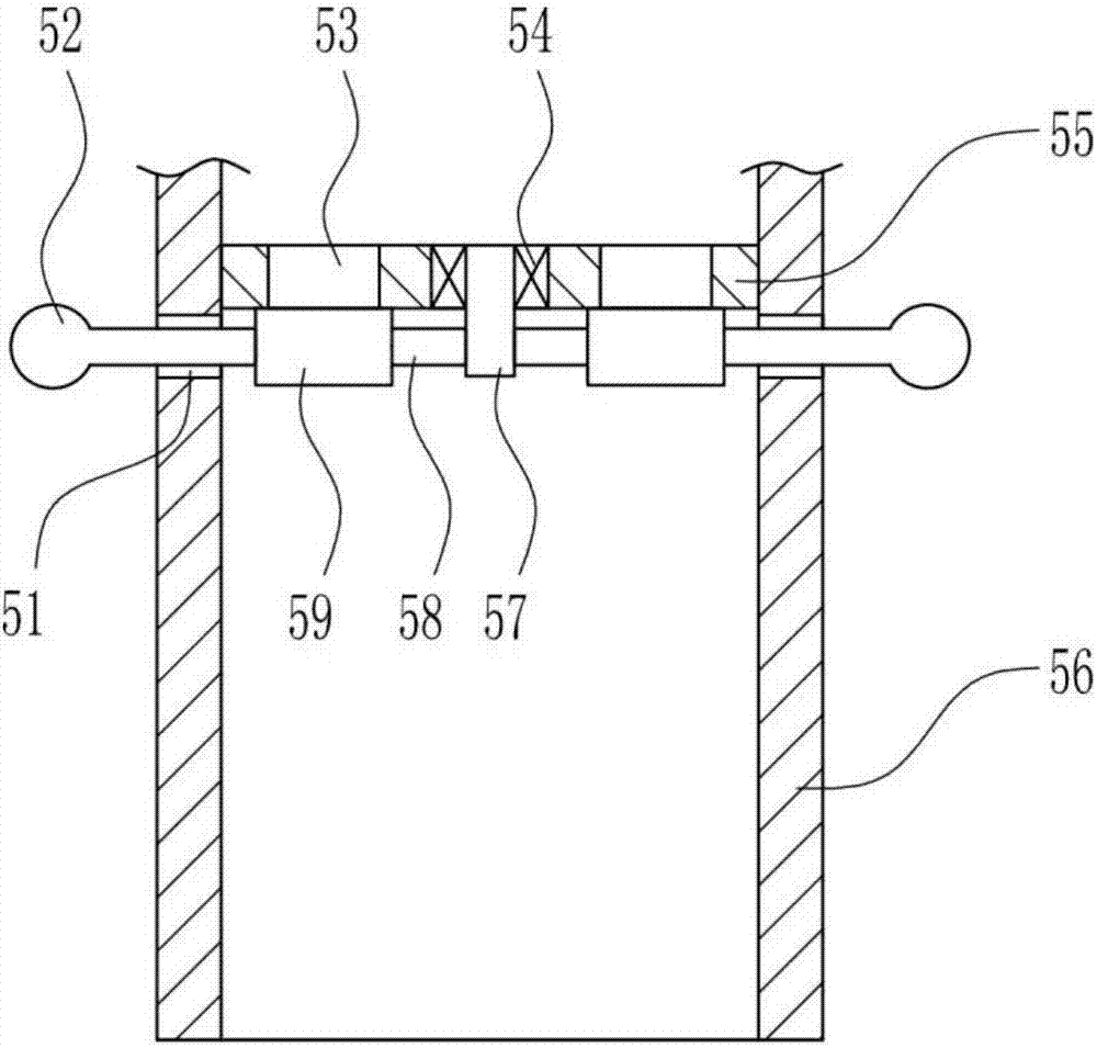
[0038] A device for preparing a fixer for imaging, such as Figure 1-9 As shown, it includes an outer box 1, a discharge pipe 2, a valve 3, a transparent feeding hopper 4, a discharging device 5, a stirring device 6, a modulation box 7 and a support rod 8, and the top wall of the outer box 1 is connected with a discharging device. 5. The top of the discharging device 5 is connected with a transparent feeding hopper 4, the transparent feeding hopper 4 is marked with a scale, a support rod 8 is symmetrically arranged on the left side of the inner top of the outer box 1, and the bottom end of the support rod 8 is connected with a modulation box 7, The modulation box 7 is made of transparent material, the modulation box 7 is connected with the bottom of the discharging device 5, and a stirring device 6 is arranged in the modulation box 7, and the stirring device 6 is connected with the inner front wall, inner rear wall and inner right wall of the outer box 1, and the modulation box...
Embodiment 2
[0040] A device for preparing a fixer for imaging, such as Figure 1-9 As shown, it includes an outer box 1, a discharge pipe 2, a valve 3, a transparent feeding hopper 4, a discharging device 5, a stirring device 6, a modulation box 7 and a support rod 8, and the top wall of the outer box 1 is connected with a discharging device. 5. The top of the discharging device 5 is connected with a transparent feeding hopper 4, the transparent feeding hopper 4 is marked with a scale, a support rod 8 is symmetrically arranged on the left side of the inner top of the outer box 1, and the bottom end of the support rod 8 is connected with a modulation box 7, The modulation box 7 is made of transparent material, the modulation box 7 is connected with the bottom of the discharging device 5, and a stirring device 6 is arranged in the modulation box 7, and the stirring device 6 is connected with the inner front wall, inner rear wall and inner right wall of the outer box 1, and the modulation box...
Embodiment 3
[0043] A device for preparing a fixer for imaging, such as Figure 1-9 As shown, it includes an outer box 1, a discharge pipe 2, a valve 3, a transparent feeding hopper 4, a discharging device 5, a stirring device 6, a modulation box 7 and a support rod 8, and the top wall of the outer box 1 is connected with a discharging device. 5. The top of the discharging device 5 is connected with a transparent feeding hopper 4, the transparent feeding hopper 4 is marked with a scale, a support rod 8 is symmetrically arranged on the left side of the inner top of the outer box 1, and the bottom end of the support rod 8 is connected with a modulation box 7, The modulation box 7 is made of transparent material, the modulation box 7 is connected with the bottom of the discharging device 5, and a stirring device 6 is arranged in the modulation box 7, and the stirring device 6 is connected with the inner front wall, inner rear wall and inner right wall of the outer box 1, and the modulation box...
PUM
 Abstract
Description
Claims
Application Information