
Method for using center calibration device of engine vibration experiment

一种中心校准、校准装置的技术,应用在发动机的测试、测量装置、位置/方向控制等方向,能够解决连接点位置同轴度不好准确判断、机体激烈震动、费时费力等问题,达到缩短实验准备时间、零件互换性强、灵活性好的效果

Inactive Publication Date: 2017-12-15
WUHU WATER PUMP MFG
View PDF6 Cites 0 Cited by
  • Summary
  • Abstract
  • Description
  • Claims
  • Application Information

AI Technical Summary

Problems solved by technology

When the engine and the dynamometer are manually connected, the coaxiality of the two connection points is not easy to accurately judge, and it is easy to have deviations, which will cause the body to vibrate violently and cause damage to the equipment
Traditional detection methods, such as the fixed-point detection method of the dial indicator, need to use the dial indicator to conduct point analysis at different positions of the engine flywheel, and then determine whether the dynamometer and the engine are coaxially connected after multiple comparisons, which is time-consuming and labor-intensive. very careful sampling

Method used


Image

  • Method for using center calibration device of engine vibration experiment
  • Method for using center calibration device of engine vibration experiment
  • Method for using center calibration device of engine vibration experiment

Examples


Embodiment Construction

[0021] The present invention will be further described below in conjunction with specific embodiments.

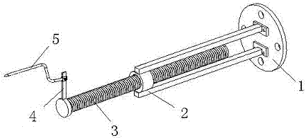
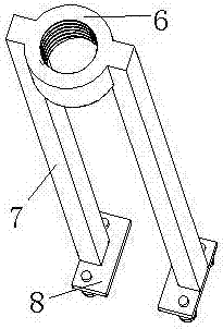
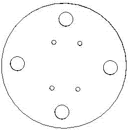
[0022] Such as figure 1 , figure 2 , image 3 , Figure 4 As shown, a central calibration device for an engine vibration experiment includes a connection plate 1, and also includes a fixed bracket 2, a screw rod 3 and a detection needle 5 arranged in sequence. The bracket fixing holes are distributed in shape, and there are installation holes on the connecting plate away from the center; the fixing bracket is fixed on the connecting plate through nuts and bolts, which includes threaded sleeves 6, supporting arms 7 and fixing plates arranged in sequence from top to bottom 8. There are two support arms 7, both of which are symmetrically fixed on both sides of the threaded sleeve 6; there are two fixed plates 8, which are respectively fixed on the bottom of the support arms, and the fixed plate 8 is a rectangular structure, on which there are 2 screw holes; the layout of ...


PUM


Abstract

The invention discloses a method for using a center calibration device of an engine vibration experiment and belongs to the field of testing tools for automobile components. In the time of use, firstly an engine is installed on a test bench according to requirements, through adjusting four support feet in front of and behind the engine, a height gauge is used to adjust the center height of the engine to be consistent with a center height of a dynamometer, a positioning plate of the device is fixed to the dynamometer, the position of a sliding sleeve in a pointer sliding rod is adjusted according to the model of the engine, fastening screws re tightened, a screw rod is rotated to adjust a protruding length, thus a tip head of a detection pin faces an outer surface of the engine flywheel, and the flatness of the engine and the dynamometer is adjusted through rotating a center shaft of the dynamometer. The device has the advantages of ingenious production, low production cost, strong interchangeability of components, labor saving, the effective reduction of the experimental cost of the engine and the shortening an experiment preparation time.

Description

[0001] The patent application of the present invention is a divisional application with application number: 2014102247367. The filing date of the original application is 2014-08-06. The name of the invention is: a central calibration device for engine vibration experiment. technical field [0002] The invention belongs to the field of detection tooling for auto parts, and more specifically relates to a method for using a central calibration device for engine vibration experiments. Background technique [0003] With the development of the automobile industry, the research and development of new engine models and new technologies have also received extensive attention and attention. In order to verify new models or new technologies, most engine manufacturers have introduced dynamometers and supporting control devices to perform various simulation operations on the engine test bench and test the output power of the engine. When the engine and the dynamometer are manually connec...

Claims


Application Information

Patent Timeline
Patent Type & Authority Applications(China)
IPC IPC(8): G05D3/00G01M15/02
CPCG01M15/02G05D3/00
Inventor 唐爱军
Owner WUHU WATER PUMP MFG
Learn More