Driving mechanism of new-energy automobile driving motor test board

A technology for new energy vehicles and driving motors, which is used in motor generator testing, electrical components, electromechanical devices, etc., can solve the problems of complex transmission structure, long transmission structure, and increased cost, and achieves simplified transmission structure, simple and convenient operation, The effect of reducing product cost

Active Publication Date: 2017-12-15
ANHUI JEE AUTOMATION EQUIP CO LTD
View PDF6 Cites 7 Cited by
  • Summary
  • Abstract
  • Description
  • Claims
  • Application Information

AI Technical Summary

Problems solved by technology

For the first form, firstly, the transmission structure is complicated, and a special high-speed bearing box needs to be designed; secondly, there are many parts used, and the overall structure cost is high, which has no economic advantages, and because the transmission structure is long, the transmission There are many components, and the coaxiality adjustment between the components is time-consuming and laborious. Finally, due to the high-speed (≥10000rpm) test requirements of the motor test, the requirements for the speed capability and dynamic balance of each transmission component are relatively high, which indirectly increases the cost.
For the second form, since the mounting bracket of the motor under test and the motor under test are separated, it is necessary for the assembler to adjust the installation coaxiality of the two motors, and since both ends of the rigid shaft are splines, one end It is difficult to form a tight fit between the spline part and the motor under test, which makes it difficult to ensure the coaxiality between the other end of the rigid shaft and the spline output shaft of the motor under test, and it will be difficult to connect the motor under test with the rigid shaft. Calibration is good for docking
Therefore, the transmission mechanism in the prior art has the contradictory problem that the structure with good coaxiality is complex and costly, or the structure is simple and low-cost but the coaxiality is difficult to guarantee.

Method used


Image

  • Driving mechanism of new-energy automobile driving motor test board
  • Driving mechanism of new-energy automobile driving motor test board
  • Driving mechanism of new-energy automobile driving motor test board

Examples


Embodiment Construction

[0023] The embodiments of the present invention are described in detail below. This embodiment is implemented on the premise of the technical solution of the present invention, and detailed implementation methods and specific operating procedures are provided, but the protection scope of the present invention is not limited to the following implementation example.

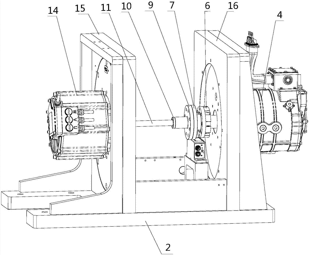
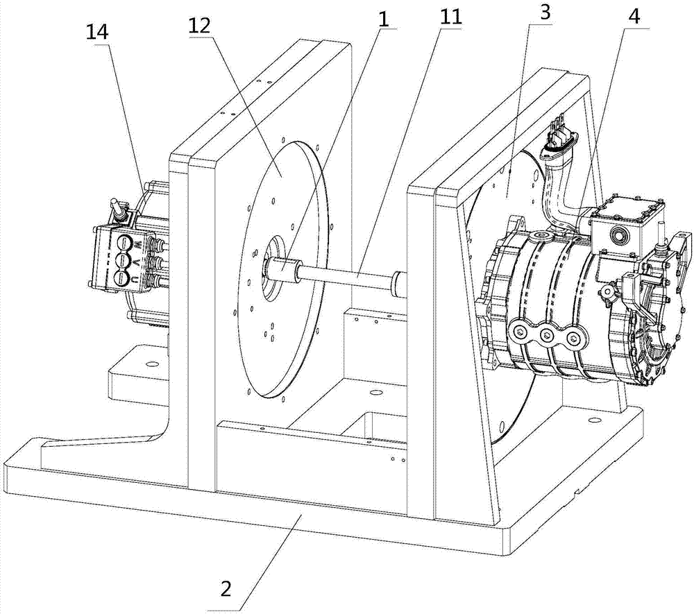
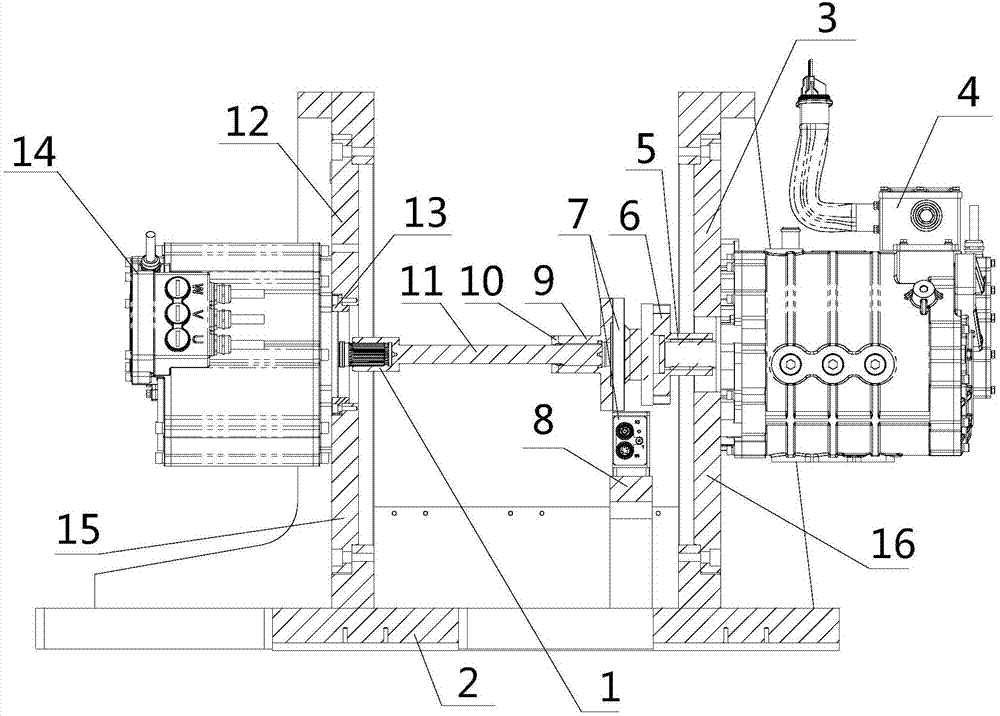
[0024] see Figure 1 to Figure 6 , this embodiment discloses a new energy vehicle drive motor test bench transmission mechanism, including a mounting bracket 2, the mounting bracket 2 is provided with a vertical first vertical plate 15 and a second vertical plate 16, the first vertical plate 15 and The second vertical board 16 is left and right oppositely arranged.

[0025] The center of the second vertical plate 16 has a second step mounting hole 18, and the second step mounting hole 18 is detachably installed with the accompanying test motor mounting plate 3, and the accompanying test motor 4 is installed on the...


PUM


Abstract

The invention discloses a driving mechanism of a new-energy automobile driving motor test board. The driving mechanism comprises a mounting support, a first vertical plate and a second vertical plate are arranged on the mounting support, a test accompanying motor is fixedly installed on the second vertical plate, and a connecting flange, a torque sensor, a spline transition sleeve and a spline connecting shaft are connected to the left end of the output shaft of the test accompanying motor in sequence; a tested motor mounting plate is installed at the center of the first vertical plate, a tested motor positioning ring is detachably installed at the center of the tested motor mounting plate, a tested motor is detachably installed on the first vertical plate, the spline connecting shaft is connected with the output shaft of the tested motor in a butt joint mode through a connecting sleeve cylinder, and the tested motor positioning ring, the output shaft of the tested motor, the spline connecting shaft, the spline transition sleeve, the connecting flange and the output shaft of the test accompanying motor are coaxially arranged. The driving mechanism has the advantages that while coaxiality of the tested motor and the test accompanying motor is ensured, the driving structure is simplified, the product cost is reduced, and high-speed running can be achieved.

Description

technical field [0001] The invention relates to a transmission mechanism of a drive motor test bench for new energy vehicles. Background technique [0002] In the transmission mechanism of the new energy vehicle drive motor test bench, the main drive is the mutual drag between the motor under test and the motor under test. There are mainly two forms in the prior art. The first form is to set up an elastic coupling and a high-speed bearing box between the motor under test and the accompanying motor, and the transmission direction is the accompanying motor-torque sensor-coupling- Bearing housing - spline tooling - motor under test. The second form is to connect a rigid shaft between the motor under test and the motor under test. The two ends of the rigid shaft are splined, which can be directly connected to the two motors. The transmission direction is the motor under test-torque sensor-spline tooling - The motor under test. [0003] All the transmission mechanisms in the p...

Claims


Application Information

Patent Timeline
Patent Type & Authority Applications(China)
IPC IPC(8): H02K7/10G01R31/34
CPCG01R31/34H02K7/10
Inventor 刘蕾姚雨龙汪波石爱文夏善伟
Owner ANHUI JEE AUTOMATION EQUIP CO LTD
Why Eureka
Try Eureka