
Method for calibrating and controlling parameters of motor

A control method and parameter calibration technology, applied in the estimation/correction of motor parameters, etc., can solve the problems of efficient control, complex calculation process, mathematical model restriction, etc., to achieve efficient and precise control, simplified mathematical model, accurate and efficient control. Effect

Active Publication Date: 2017-12-15
SUZHOU AMTF ROBOTS CO LTD
View PDF6 Cites 2 Cited by
  • Summary
  • Abstract
  • Description
  • Claims
  • Application Information

AI Technical Summary

Problems solved by technology

[0003] The calculation process is very complicated, and it is difficult to verify the settings of parameters and constants (coefficients) involved in the process. In addition, the algorithm mainly aims at the control performance of the motor. Although it can obtain better dynamic response performance of speed and torque, the It cannot have high efficiency under all speed and load conditions, because it is not only the law and amplitude of the three phases that affect the efficiency of the motor, but also the PWM frequency of the modulation wave, the induced electromotive force at different speeds on the voltage and current angle, and the motor stator. Influenced by many factors such as the magnetic flux change caused by the rotor air gap and other factors, as well as the performance and efficiency differences at different speeds and torques caused by other unknown factors, these will cause the conventional method to fail to maximize the performance of the motor under various working conditions. have good efficiency
As a power motor, efficiency is a crucial parameter under the premise of meeting the requirements of torque, power, speed, etc. Therefore, the current three-phase motor control method has insufficient power motor efficiency, which is not conducive to energy saving
[0004] In addition, the existing calibration and control method of obtaining current through the speed and torque index look-up table only solves the problem of the accuracy of motor torque control, and its current control still needs to use the above-mentioned vector control method, and there are still complex calculation processes and limitations. Due to the constraints of the mathematical model, it is impossible to achieve efficient control of the motor

Method used


Image

  • Method for calibrating and controlling parameters of motor
  • Method for calibrating and controlling parameters of motor
  • Method for calibrating and controlling parameters of motor

Examples


Embodiment Construction

[0023] In order to better understand the technical content of the present invention, specific embodiments are given together with the attached drawings for description as follows.

[0024] Described method example by bench test:

[0025] Composition: The target motor is connected to the dynamometer through the torque sensor (the dynamometer has at least the function of controlling the speed), the dynamometer is used to control the motor output shaft to run stably at the set speed, and the torque sensor is used to measure the output of the target motor torque.

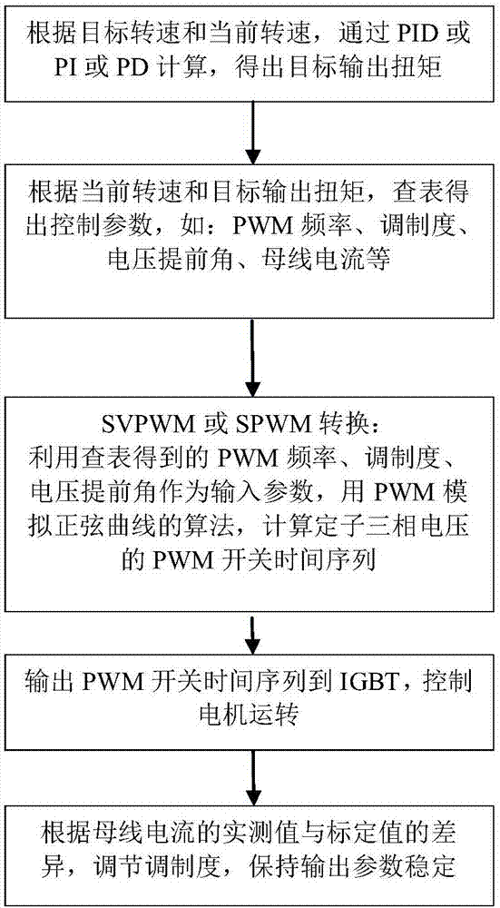
[0026] Calibration steps (such as figure 2 ):

[0027] First set the speed of the dynamometer at a target value;

[0028] Set a minimum target torque;

[0029] Then, start the target motor through a set of initial control parameters;

[0030] Change the control parameters of the target motor one by one or at the same time, by comparing the input power, obtain the control parameters of the motor corresponding to th...


PUM


Abstract

A method for calibrating and controlling parameters of a motor includes the steps of calibration and motor control. The method includes the following steps that through an experiment, complex control parameters required by motor control are linearized into a corresponding control parameter data table using torque and speed as conditions, a current sensor and the like are used for correcting performance deviation caused by the influence of other conditions, accurate and efficient motor control is achieved, a mathematical model required by the motor control is simplified, limitations of the mathematical model on motor control are overcome, and efficient and accurate control over the motor is achieved.

Description

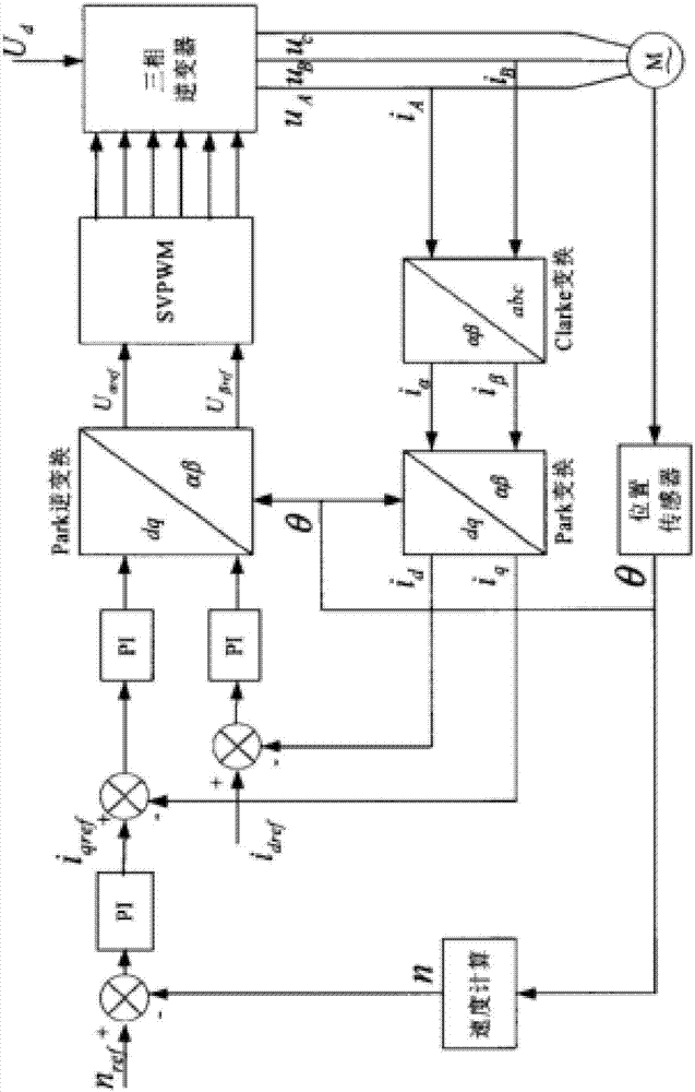
technical field [0001] The invention relates to the field of motor control, in particular to a method for controlling a motor. Background technique [0002] With the development of industry and new energy vehicles, the application of three-phase motors is becoming more and more extensive. At present, vector control technology is generally used to convert the magnetic field coordinate system formed by three-phase electricity into a magnetic field coordinate system similar to that of DC motors. The excitation current and the torque current are separated, and then the calculation method similar to that of the DC motor (the input current is proportional to the torque) is used to realize the control of the speed or torque of the three-phase motor, such as figure 1 As shown, the control method needs to use the current sensor to measure the current of each phase, and then perform Clarke transformation (convert the three-phase stationary coordinate system into a two-phase stationary...

Claims


Application Information

Patent Timeline
IPC IPC(8): H02P23/14
CPCH02P23/14
Inventor 林中尉
Owner SUZHOU AMTF ROBOTS CO LTD
Learn More