Method for welding compressor shell

A compressor shell and welding method technology, which is applied in welding equipment, welding equipment, auxiliary welding equipment, etc., can solve problems such as too thin plate thickness, small shell diameter, and difficult welding

Inactive Publication Date: 2017-12-19
RECHI PRECISION
View PDF7 Cites 3 Cited by
  • Summary
  • Abstract
  • Description
  • Claims
  • Application Information

AI Technical Summary

Problems solved by technology

Regardless of the welding method of horizontal welding or vertical welding, during metal fusion welding, due to the effect of gravity, the molten metal 102 (metal molten soup) is prone to bias current, and the molten metal 102 will be left or right. The machine time is particularly obvious, because the small diameter and large curvature of the shell of the small compressor make it difficult to weld in the existing way, no matter vertical or horizontal welding, because the outer diameter becomes smaller or the thickness of the plate is too thin, resulting in poor weld bead
[0003] Furthermore, the existing horizontal welding and vertical welding, when the short-circuit current occurs, the angle with the welding torch 103 can not produce a good uniform conduction, and the shielding gas is not easy to cover

Method used


Image

  • Method for welding compressor shell
  • Method for welding compressor shell
  • Method for welding compressor shell

Examples


no. 1 example

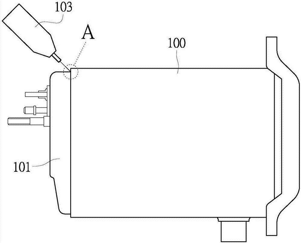
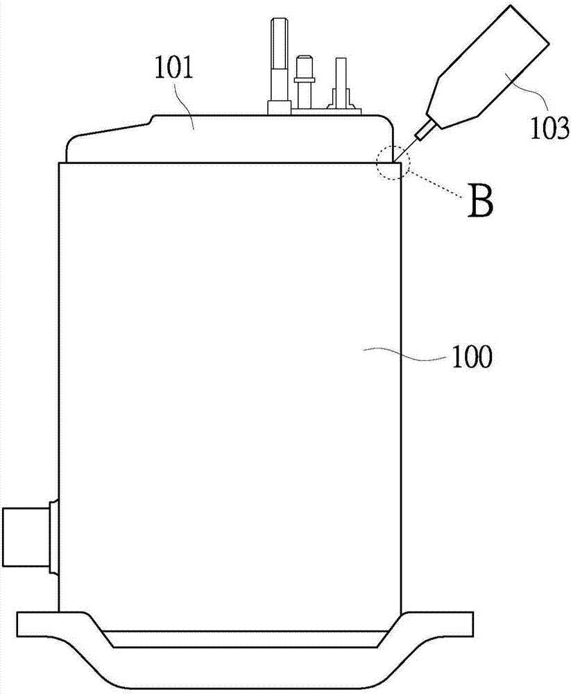
[0029] see Figure 5 , the present invention provides a welding method for a compressor shell, in particular relates to a welding method for a main shell of a compressor and a top cover and a bottom cover. The size of the compressor shell is not limited and can be applied to various sizes The compressor housing, the welding method of the compressor housing includes the following steps:

[0030] First, the cover body 2 of a compressor is lapped on one end of the main casing 1 (such as Image 6 and Figure 7 shown), and as mentioned above, the size of the main housing 1 and the cover 2 is not limited. In this embodiment, the thickness of the plates of the main housing 1 and the cover 2 are all below 2.5 mm. The cover 2 It can be a top cover or a bottom cover, that is, both the top cover and the bottom cover of the compressor can be respectively welded to the main casing 1 by using the welding method of the present invention.

[0031] The main housing 1 and the cover 2 define ...

no. 2 example

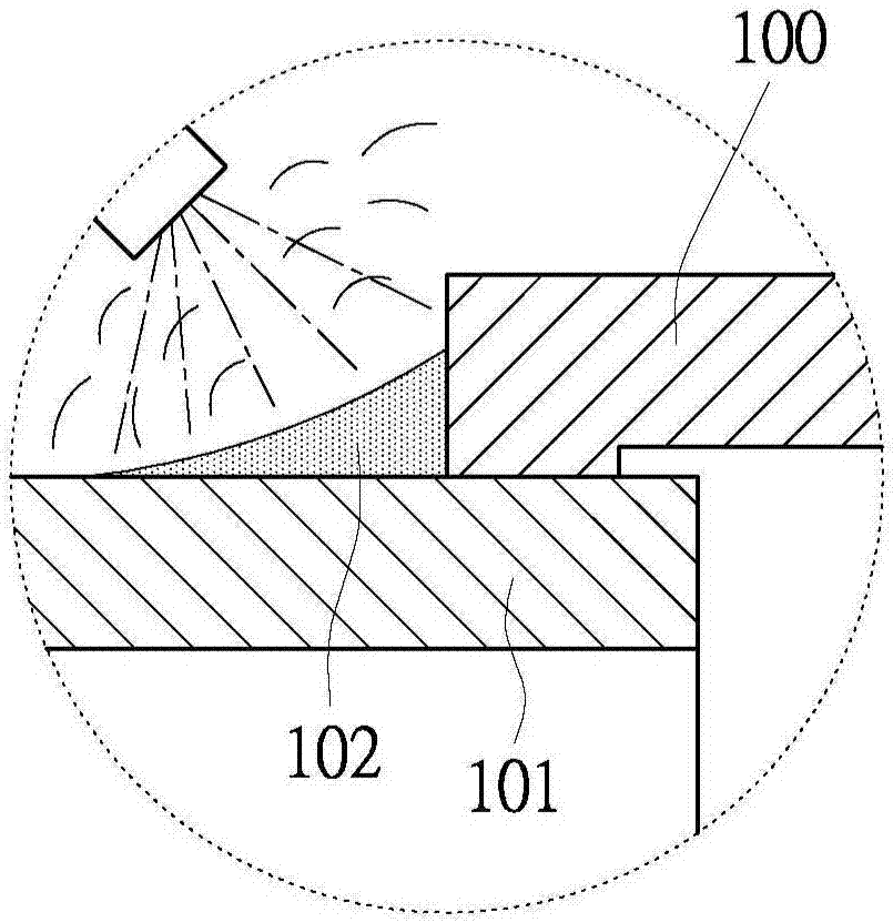
[0039] see Figure 8, in this embodiment, it can be further defined that one end of the main housing 1 and the cover 2 has a housing end surface 9 , and the housing end surface 9 can include the outer end surfaces of the cover 2 and the main housing 1 . The housing end face 9 can be a circular end face, and when the main housing 1 and the cover body 2 form an inclined setting, the housing end face 9 also forms an inclined state (such as Image 6 shown).

[0040] The central axis 3 intersects the housing end face 9 at a center point 91 of the end face. The housing end face 9 defines a transverse line 92 and a longitudinal line 93 . The transverse line 92 and the longitudinal line 93 intersect at the end face center point 91 . The transverse line 92 is parallel to the horizontal plane 4 and the longitudinal line 93 is perpendicular to the transverse line 92 . Define the outer diameter of the shell end face 9 as D, the distance between one end of the electrode 51 of the welding...


PUM

PropertyMeasurementUnit
Lengthaaaaaaaaaa

Abstract

The invention discloses a method for welding a compressor shell. The method comprises the following steps: a cover body of a compressor is connected to one end of a main shell in a lap joint mode; the main shell and the cover body define a central axis; the included angle between the central axis of the main shell and the cover body and the horizontal plane ranges from 10 degrees to 80 degrees; the main shell and the cover body rotate along the central axis; and the welding gun is arranged at the position above a lap joint of the main shell and the cover body, and welds the lap joint of the main shell and the cover body, so that the main shell and the cover body are welded to be combined. Therefore, molten metal can be guided not to be deflected, and can be uniformly distributed at a preset position.

Description

technical field [0001] The invention relates to a welding method for a compressor shell, in particular to a welding method for a main shell of a compressor and a top cover and a bottom cover. Background technique [0002] The welding of the main casing 100 of the existing compressor and the cover body 101 (comprising the top cover and the bottom cover) has always been using horizontal welding (such as figure 1 and figure 2 shown) or vertical welding (such as image 3 and Figure 4 shown). Regardless of the welding method of horizontal welding or vertical welding, during metal fusion welding, due to the effect of gravity, the molten metal 102 (metal molten soup) is prone to bias current, and the molten metal 102 will be left or right. The machine time is particularly obvious, because the small diameter and large curvature of the shell of the small compressor make the welding difficult in the existing method, no matter vertical or horizontal welding, the outer diameter be...

Claims


Application Information

Patent Timeline
IPC IPC(8): B23K31/02B23K37/00
CPCB23K31/02B23K37/00
Inventor 邱忠本曹文昌
Owner RECHI PRECISION
Why Eureka
Try Eureka