Method for forming dynamic grating stripes

A technology of dynamic grating and grating stripes, applied in the direction of using optical devices, measuring devices, instruments, etc., can solve the problems of difficult adjustment, poor measurement resolution of the film thickness to be measured, and inability to accurately measure the thickness of the film to be measured.

Inactive Publication Date: 2005-01-19
RITDISPLAY
View PDF0 Cites 2 Cited by
  • Summary
  • Abstract
  • Description
  • Claims
  • Application Information

AI Technical Summary

Problems solved by technology

Therefore, the known technology cannot provide a narrower frequency surface ultrasonic signal, and the signal/noise ratio (S/N) is low, which leads to poor resolution of the thickness measurement of the film to be measured
[0009] (2) It is extremely difficult to adjust the incident angles of the two pulsed lasers to be consistent, so it is known that due to the inconsistent incident angles, it is often difficult to accurately determine the distance between bright and dark grating stripes or the wavelength of the surface ultrasonic waves, or even produce grating stripes. And other proble

Method used


Image

  • Method for forming dynamic grating stripes
  • Method for forming dynamic grating stripes
  • Method for forming dynamic grating stripes

Examples


Embodiment Construction

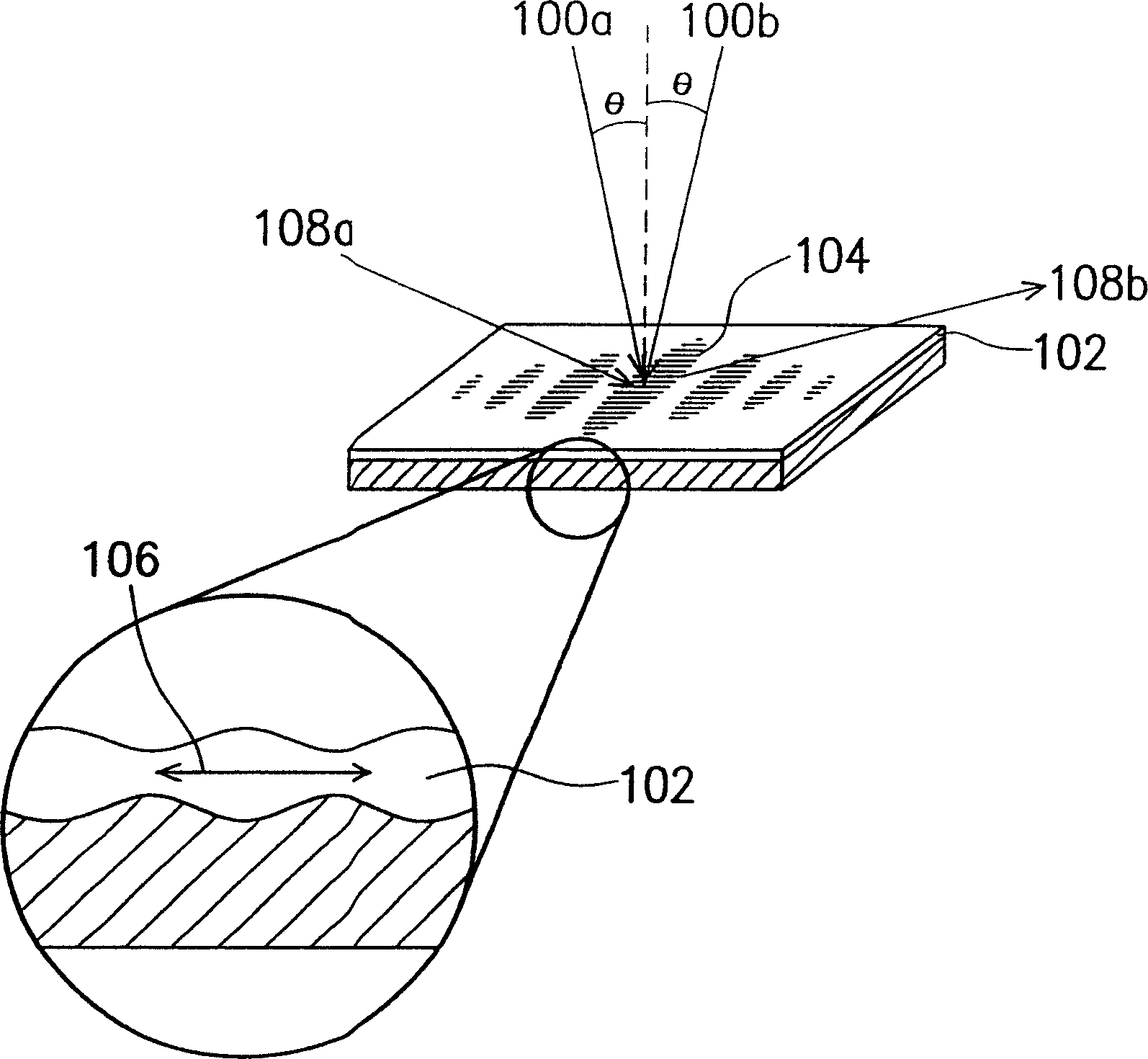
[0045]This embodiment will take a film thickness measurement as an example for illustration, but it does not limit that the method for forming the dynamic grating stripes of the present invention is only applicable to the film thickness measurement. In short, the method for forming dynamic grating stripes disclosed in this embodiment can be applied to a transient SAW device (transient SAW device), which is a kind of sensor, and it can not only be applied to material properties ( The measurement on material characterization) can also be applied to the field of biochemistry (Bio-chemical). Among them, the measurement of material properties includes, for example, the material properties of films or fluids, and biochemical applications such as mass loading (Massloading), mechanical properties (Mechanical properties), rheological properties (Rheological properties), electrical properties (Electrical properties) properties), thermal effect (Thermal effect) and so on.

[0046] The k...


PUM


Abstract

A forming method for dynamic grating fringe provides base materials with polishing surface located with multiple reflection areas. Then it is to provide a laser and to let laser shoot on the reflection areas of base materials and forms a grating fringe after intervention.

Description

technical field [0001] The present invention relates to a method for forming a dynamic grating pattern (laser induced grating pattern), and in particular to a method for incident optical interference strain gauge (Interference Strain / Displacement Gage, ISDG) by pulse laser (pulse laser) A method to generate dynamic grating stripes. Background technique [0002] With the continuous progress of the semiconductor industry, integrated circuits are constantly moving towards the direction of miniaturization and high operating efficiency. In order to meet the needs of miniaturization and high operating efficiency at the same time, the integration of integrated circuits must become more critical. . Since the functions of integrated circuits are increasingly diversified, the design also tends to be a multi-layer design. In the manufacturing process of integrated circuits, processes such as deposition, lithography, etching, and chemical mechanical polishing (CMP) are often used. Bas...

Claims


Application Information

Patent Timeline
IPC IPC(8): G01B9/02G01B11/06
Inventor 廖建硕
Owner RITDISPLAY
Why Eureka
Try Eureka