Paper grabbing mechanism of paper unloading machine

A paper machine and paper technology, which is applied in the field of unloading machine paper grabbing mechanism, can solve the problems of unfavorable effects of stacked paper packaging, inability to ensure the consistency of paper stacks, and paper stack offsets.

Inactive Publication Date: 2017-12-19
ZHEJIANG HUAYUE PACKING MACHINERY
View PDF7 Cites 3 Cited by
  • Summary
  • Abstract
  • Description
  • Claims
  • Application Information

AI Technical Summary

Problems solved by technology

But the prior art has the same problem as follows: since the left and right lateral movement of the paper transfer table, the left paper stop arm and the right paper stop arm are independently driven by their respective motors, when the stack of paper to be stacked on the paper transfer table moves along with the paper When the transfer table and the left and right paper stop arms move horizontally together, since the actions of the paper transfer table and the left and right paper stop arms cannot be completely synchronized, it is inevitable that the paper stack will deviate, causing the paper stack to reach the stacking position. Deviation; more seriously, when the paper transfer table moves above the paper stacking position and is pulled out, the paper unloading guide surface of the paper transfer table will first leave contact with the paper pile, so the end of the paper pile sags, The side of the end of the paper pile is tilted on one side, resulting in uneven side edges of the paper pile on the paper pile. In addition, the position of the paper pile itself is shifted during the transfer process, so the consistency of the paper stack cannot be guaranteed. It will result in poor stacking quality of the paper stack. Even if the sides of the paper stack are patted with the left and right cardboard stoppers, there will be little alignment effect, which will adversely affect the subsequent packaging and use of the stacked paper.

Method used


Image

  • Paper grabbing mechanism of paper unloading machine
  • Paper grabbing mechanism of paper unloading machine

Examples


Embodiment Construction

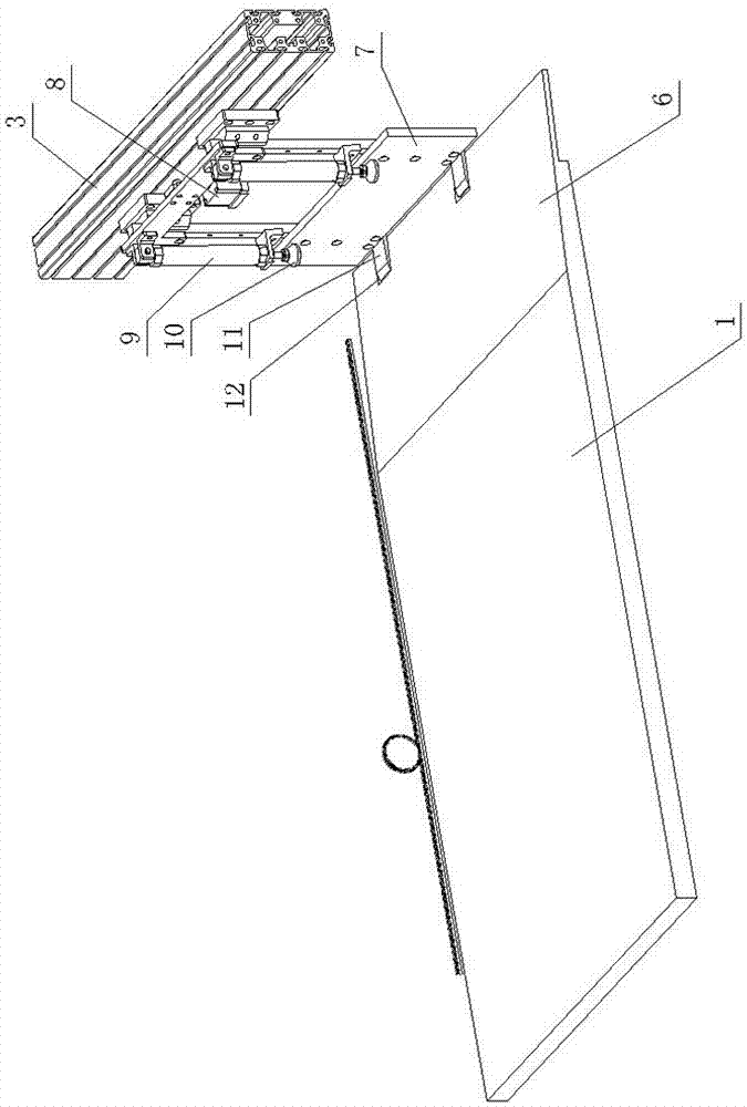
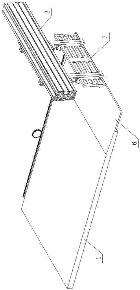
[0011] As shown in the figure, the paper grabbing mechanism of the paper unloader of the present invention includes a lifting beam, a paper transfer table 1 and a right paper retaining arm 3, and the paper transfer table 1 and the right paper retaining arm 3 are installed on the lifting beam and respectively Driven by the driving motor, it moves independently in the left and right directions. The table top of the paper transfer table 1 has a downwardly inclined paper unloading guide surface 6 at the right end. The right paper stop arm 3 is connected to the right paper stop plate 7. The rightmost end of the paper unloading guide surface 6 is set There are two gaps 12 at the front and back, and a paper-picking block 11 is movable in the gap 12. The paper-picking block 11 is arranged at the bottom of the right paper blocking plate 7 and is fixedly connected with the right paper blocking plate 7. The paper picking block 11 and the right paper blocking plate 7 are jointly formed by ...


PUM


Abstract

The invention discloses a paper grabbing mechanism of a paper unloading machine. The paper grabbing mechanism comprises a lifting cross beam, a paper transfer table and a right paper blocking arm. The paper transfer table and the right paper blocking arm are mounted on the lifting cross beam and driven by respective drive motors to move left and right independently. A downwards-inclining paper unloading guiding face is arranged at the right end of the table surface of the paper transfer table, and the right paper blocking arm is connected with a right paper baffle. The paper grabbing mechanism is characterized in that a notch is formed in the rightmost end of the paper unloading guiding face, a paper grabbing block is movably arranged in the notch and arranged at the bottom of the right paper baffle, the paper grabbing block is pushed by a paper grabbing cylinder to move up and down, a paper pressing block is arranged above the paper grabbing block and pushed by a right cylinder to move up and down, and the paper grabbing cylinder and the right cylinder are connected to the right paper blocking arm. Paper stacking consistency during paper unloading can be guaranteed, the paper stacking quality is improved, and subsequent packaging is facilitated.

Description

technical field [0001] The invention relates to a paper unloading device for automatically stacking and collecting paper, in particular to a paper grabbing mechanism of a paper unloader. Background technique [0002] After the paper cutter cuts the paper, the paper needs to be stacked and collected, and then packed for subsequent production. At present, a paper unloading machine has been used to automatically stack and collect the above-mentioned papers, such as the patent titled "paper automatic stacking equipment" applied for by the applicant on December 3, 2014. But the prior art has the same problem as follows: since the left and right lateral movement of the paper transfer table, the left paper stop arm and the right paper stop arm are independently driven by their respective motors, when the stack of paper to be stacked on the paper transfer table moves along with the paper When the transfer table and the left and right paper stop arms move horizontally together, sinc...

Claims


Application Information

Patent Timeline
Patent Type & Authority Applications(China)
IPC IPC(8): B65G47/90
CPCB65G47/90
Inventor 王建彪夏碎娒倪晓静黄仁众林希望高泉全
Owner ZHEJIANG HUAYUE PACKING MACHINERY
Why Eureka
Try Eureka