Heat coupling compression absorption type waste heat recovering type heat pump circulation system and method

A circulation system and absorption cycle technology, applied in the field of circulation system, can solve the problems of consumption, low efficiency, system consumption, etc.

Active Publication Date: 2017-12-19
SHANGHAI JIAO TONG UNIV
View PDF5 Cites 7 Cited by
  • Summary
  • Abstract
  • Description
  • Claims
  • Application Information

AI Technical Summary

Problems solved by technology

However, compression heat pumps and absorption heat pumps also have their own problems. For example, although compression heat pumps have high efficiency when raising the temperature of waste heat, the system consumes high-grade electric energy,

Method used


Image

  • Heat coupling compression absorption type waste heat recovering type heat pump circulation system and method
  • Heat coupling compression absorption type waste heat recovering type heat pump circulation system and method
  • Heat coupling compression absorption type waste heat recovering type heat pump circulation system and method

Examples


Embodiment 1

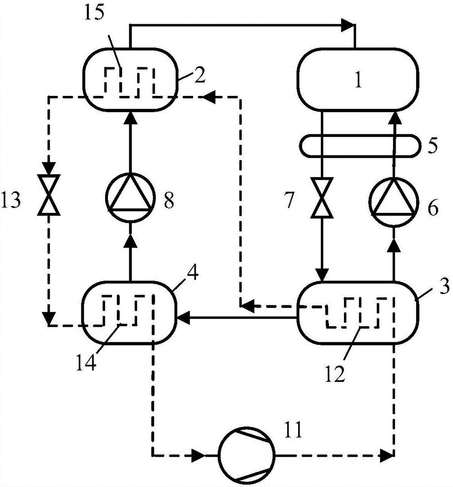
[0120] The circulatory system provided by the present invention is in the first working mode, that is, when the first working mode circulates, the component structure is as follows: figure 1 As shown, the main internal heat exchange of the cycle system operating in the first working mode is as follows: the first compression cycle condenser 12 exchanges heat with the generator 3, and the second compression cycle condenser 15 exchanges heat with the absorption cycle evaporator 2. Heat exchange, the absorption cycle condenser 4 and the compression cycle evaporator 14 perform heat exchange, the solution entering the absorber 1 from the solution pump 6 and the solution entering the first throttle valve 7 from the absorber are exchanged in the solution heat recovery device 5 hot. The external heat exchange of the circulation system is as follows: waste heat is input to the compression cycle evaporator 14, and the absorber 1 outputs heat to the outside.

[0121]When the circulation ...

Embodiment 2

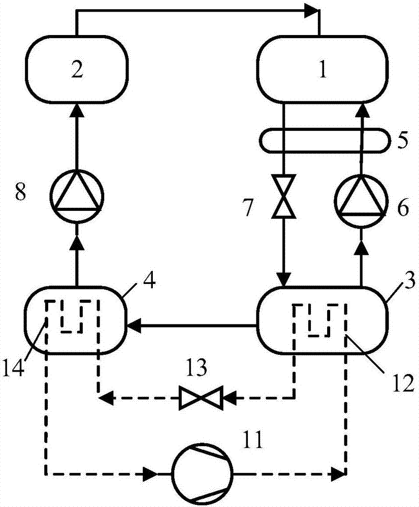
[0124] When the circulatory system circulates in the second working mode, that is, the second working mode, the structure of the components is as follows: figure 2 As shown, the main internal heat exchange of the circulation system operating in the second working mode is as follows: the first compression cycle condenser 12 exchanges heat with the generator 3, and the absorption cycle condenser 4 exchanges heat with the compression cycle evaporator 14. Heat, the solution entering the absorber 1 from the solution pump 6 and the solution entering the first throttling valve 7 from the absorber perform heat exchange in the solution heat recovery device 5 . The heat exchange between the circulation system and the outside world is as follows: heat from the environment is input to the compression cycle evaporator 14, waste heat is input to the absorption cycle evaporator 2, and the absorber 1 outputs heat to the outside.

[0125] When the system circulates in the second working mode,...

Embodiment 3

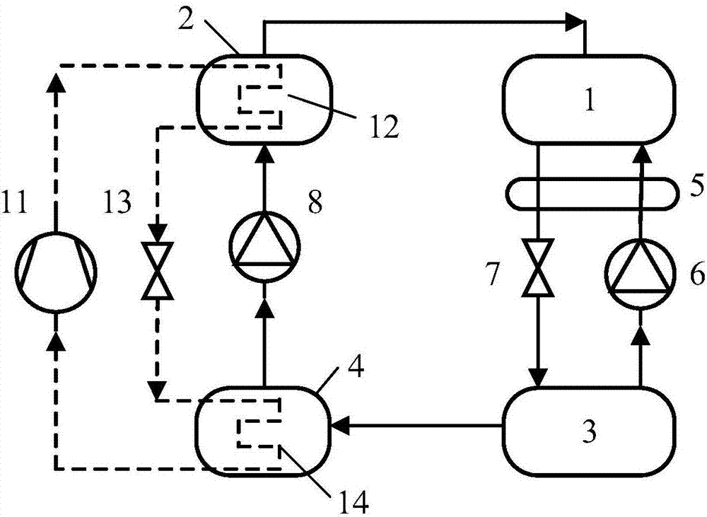
[0127] When the replacement system operates in the third working mode, that is, when the third working mode cycles, the structure of the components is as follows: image 3 As shown, the main internal heat exchange of the circulation system is as follows: the heat exchange between the compression cycle condenser 12 and the absorption cycle evaporator 2, the heat exchange between the absorption cycle condenser 4 and the compression cycle evaporator 14, and the solution pump 6 enters the absorber 1 solution and the solution entering the throttling valve 7 from the absorber perform heat exchange in the solution heat recovery device 5 . The heat exchange between the system and the outside is as follows: the ambient heat is input to the compression cycle evaporator 14, the waste heat is input to the generator 3, and the absorber 1 outputs heat to the outside.

[0128] When the system circulates in the third working mode, the internal working fluid flow of the compression heat pump s...


PUM


Abstract

The invention provides a heat coupling compression absorption type waste heat recovering type heat pump circulation system. The heat coupling compression absorption type waste heat recovering type heat pump circulation system comprises a compression heat pump subcycle system and an absorption heat pump subcycle system; the compression heat pump subcycle system comprises a compression machine (11), a first compression circulation condenser (12), a second compression circulation condenser (15) and a compression circulation evaporator (14); the absorption heat pump subcycle system comprises an absorber, a generator (3), a solution pump (6), a cooling medium pump (8), an absorption circulation condenser (4), an absorption circulation evaporator (2) and a solution heat recovery device (5). The invention further provides a heat coupling compression absorption type waste heat recovering type heat pump circulation method. A solution for improving compression heat pump temperature rise capacity and the absorption heat pump efficiency is provided, and an efficiency circulation manner is provided for waste heat recovering.

Description

technical field [0001] The invention relates to a circulation system, in particular to a thermally coupled compression absorption waste heat recovery heat pump circulation system and a method thereof. Background technique [0002] Energy issues and environmental issues are two major problems plaguing human society today. The discharge of industrial waste heat is one of the typical problems. On the one hand, the discharge of these waste heat requires additional cooling facilities, and on the other hand, it also causes a lot of energy waste. Due to the low temperature of industrial waste heat, it is difficult to directly reuse it, so most of the waste heat is discharged to the environment through cooling towers or air cooling. In order to improve the energy waste caused by industrial waste heat discharge, the heat pump technology of waste heat recovery can be used to improve the grade of waste heat and then reuse it. On the one hand, it can reduce energy waste, and on the othe...

Claims


Application Information

Patent Timeline
IPC IPC(8): F25B30/02F25B30/04
CPCF25B30/02F25B30/04Y02P80/15
Inventor 徐震原王如竹潘权稳
Owner SHANGHAI JIAO TONG UNIV
Why Eureka
Try Eureka