
Sleeve head positioning and drilling mechanism

A technology of drilling mechanism and positioning mechanism, which is applied in the direction of boring/drilling, drilling/drilling equipment, boring machine/drilling machine parts, etc. Low production efficiency and other problems, to achieve the effect of simple structure, conducive to popularization and use, and small space occupation

Active Publication Date: 2017-12-22
ZHEJIANG SEOKHO ROBOT TECH CO LTD
View PDF5 Cites 6 Cited by
  • Summary
  • Abstract
  • Description
  • Claims
  • Application Information

AI Technical Summary

Problems solved by technology

Due to the particularity of the shape of the sleeve head H, there is no better device in the prior art to position it to process the mounting hole H4. Therefore, during the processing of the sleeve head H, it is basically transferred and placed to the On the tooling, then drill the sleeve head H that has not been processed with the mounting hole H4, and then manually take it out after the drilling is completed, and proceed to the processing of the next sleeve head H, which cannot be fully automated, and its production Labor costs are too high, production efficiency is low, and high standards of assembly operations cannot be implemented

Method used


Image

  • Sleeve head positioning and drilling mechanism
  • Sleeve head positioning and drilling mechanism
  • Sleeve head positioning and drilling mechanism

Examples


Embodiment Construction

[0021] Specific embodiments of the present invention will be described in detail below in conjunction with the accompanying drawings.

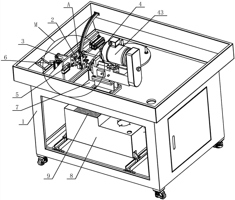
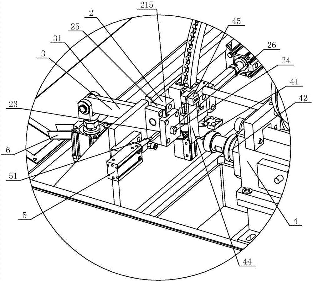
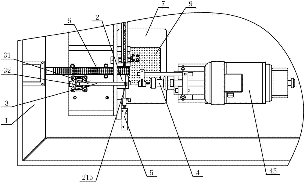
[0022] Such as Figure 1-5 Shown is a specific embodiment of the sleeve head positioning drilling mechanism of the present invention. This embodiment includes a frame 1 and a sleeve head limiting tool 2 installed on the frame 1, a positioning mechanism 3, a drilling mechanism 4 and a pushing mechanism 5, and the sleeve head limiting tool 2 is provided with an accommodating sleeve The limit cavity 21 of the head, the limit cavity 21 is provided with a material inlet 22 on one side in the length direction, and the opposite side of the material inlet 22 is provided with a top material hole 23, and the limit cavity 21 is set on one side in the width direction. Boring 24, the top of spacer cavity 21 offers gap 25; Drilling mechanism 4 is oppositely set with going into drilling hole 24, and drilling mechanism 4 comprises the drill bit 41 that can e...


PUM


Abstract

The invention discloses a sleeve head positioning and drilling mechanism. A sleeve head limiting tool of the sleeve head positioning and drilling mechanism charges laterally; after charging, a sleeve head is pressed by a pressure block of an upper positioning mechanism; a drill bit of a lateral drilling mechanism extends into to drill; after drilling, the drill bit is withdrawn and the pressure block is withdrawn; the sleeve head is pushed out from a charge hole through a pushing mechanism opposite to the charge hole; and after dropping, the sleeve head is output from a discharge path. The sleeve head positioning and drilling mechanism is simple in structure, greatly reduces investment of cost, does not need a complex mechanical hand structure to clamp and convey the sleeve head, and is only matched with a conveying mechanism for conveying the sleeve head to a position in front of the charge hole, so that the sleeve head is pushed into a limiting cavity; and a relatively great space for arranging a positioning mechanism, a drilling mechanism and a pushing mechanism is arranged at the other three sides, so that the integral structure is conveniently mounted. The sleeve head positioning and drilling mechanism improves degree of automation in a sleeve head processing process, can save labor power, improves producing and processing efficiency, and can guarantee processing quality of products.

Description

technical field [0001] The invention relates to a workpiece processing device, in particular to a sleeve head positioning drilling mechanism. Background technique [0002] Socket head H is a special tool for tightening or loosening screws. Socket head H is used together with a socket wrench. There are many different types of metric nuts on the market. Generally, socket heads H of different specifications are used together to loosen and tighten metric nuts of different specifications. Such as Figure 6 As shown, one end of the sleeve head H is a square joint H3 in the shape of a column that is clamped with the sleeve, and the other end is a sleeve hole H5 that is sleeved with a nut in a cylindrical shape and has an inner hexagonal shape. The square joint H3 Elastic steel balls are arranged on one of the sides, and the sleeve head H is preset with a mounting hole H4 on one side of the square joint H3, and the spring and steel balls are sequentially pressed into the mounting h...

Claims


Application Information

Patent Timeline
IPC IPC(8): B23B41/00B23B47/00B23Q7/06B23Q7/08
CPCB23B41/00B23B47/00B23Q7/06B23Q7/08Y02P70/10
Inventor 俞兴洪灵程旗凯陈源通陈卸件王京余晓春朱振潘浩雷张庆权黄小健陈艳丽金璐洪丰
Owner ZHEJIANG SEOKHO ROBOT TECH CO LTD
Learn More