
Reliability testing method and device of industrial robot

A technology of industrial robots and test methods, which is applied in the field of industrial robot reliability test methods and devices, can solve problems such as weakened control capabilities, disconnected production processes, and insufficient motion precision of industrial robots, so as to ensure reliability, realize motion accuracy, and realize The effect of effective control

Inactive Publication Date: 2017-12-22
重庆鲁班机器人技术研究院有限公司
View PDF6 Cites 2 Cited by
  • Summary
  • Abstract
  • Description
  • Claims
  • Application Information

AI Technical Summary

Problems solved by technology

In the existing production process, it often occurs that the control ability of industrial robots is weakened due to insufficient motion precision, and each production process cannot be effectively controlled, resulting in a phenomenon that the production process is out of touch.
[0004] In summary, at present, there is no effective solution to the problem that the motion accuracy of industrial robots cannot be accurately realized

Method used


Image

  • Reliability testing method and device of industrial robot
  • Reliability testing method and device of industrial robot
  • Reliability testing method and device of industrial robot

Examples


Embodiment 1

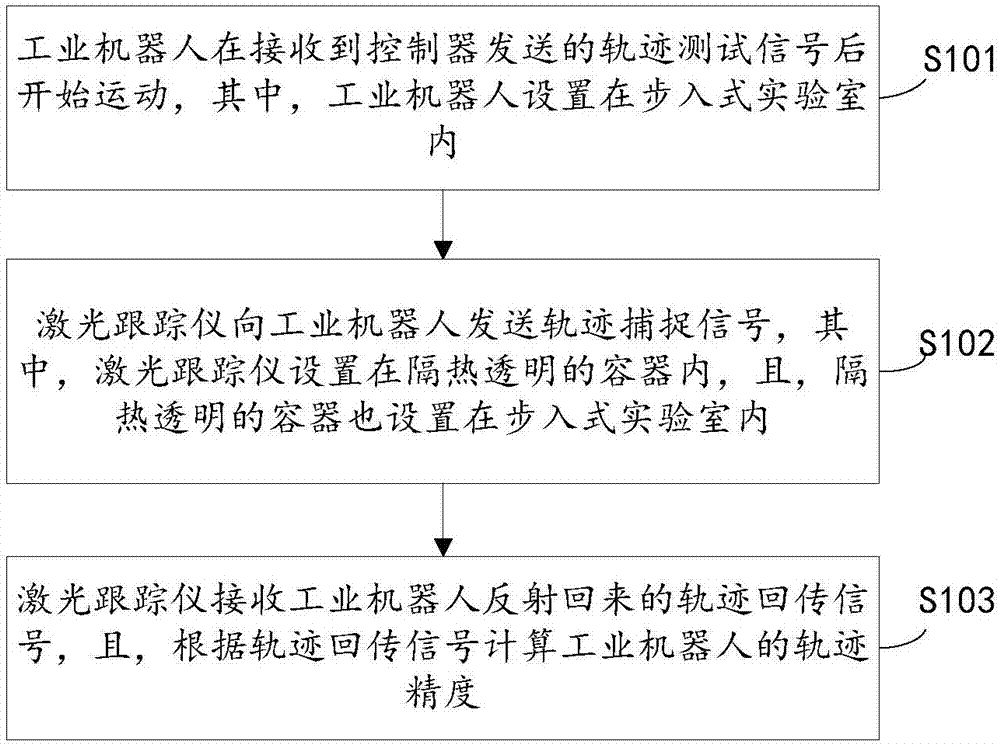
[0053] see figure 1 The industrial robot reliability test method proposed in this embodiment specifically includes the following steps:

[0054] Step S101: The industrial robot starts to move after receiving the trajectory test signal sent by the controller, wherein the industrial robot is set in the walk-in laboratory. What needs to be explained here is that the walk-in laboratory in this method is 250 square meters to ensure that industrial robots have enough space for movement.

[0055] Step S102: The laser tracker sends a trajectory capture signal to the industrial robot, wherein the laser tracker is set in a heat-insulated and transparent container, and the heat-insulated and transparent container is also set in the walk-in laboratory. What needs to be explained here is that usually, the heat-insulating transparent container is a heat-insulating glass hut, and the temperature inside the heat-insulating glass hut is kept constant, and the shape and volume of the heat-insu...

Embodiment 2

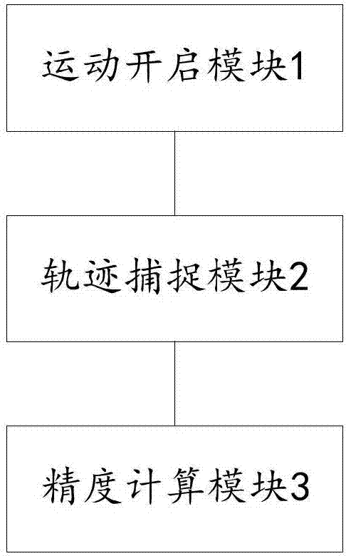
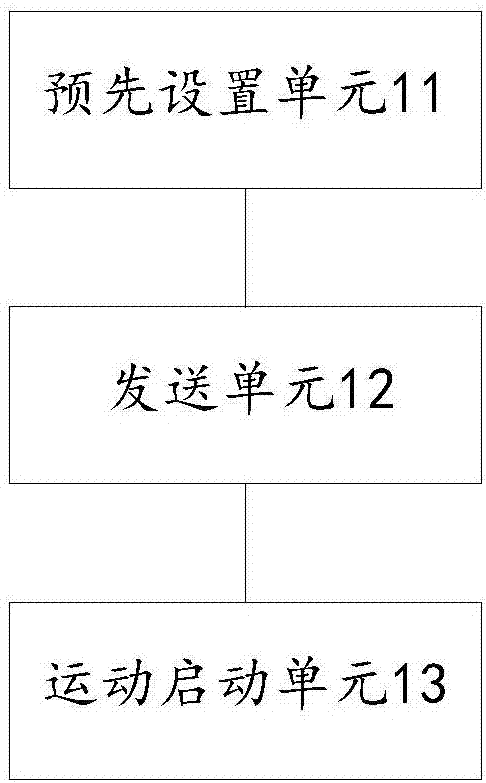
[0071] see figure 2 , image 3 and Figure 4 , the present embodiment provides an industrial robot reliability test device comprising: a sequentially connected motion opening module 1, a trajectory capture module 2 and an accuracy calculation module 3. After the trajectory test signal starts to move, wherein the industrial robot is set in the walk-in laboratory, the trajectory capture module 2 is used for the laser tracker to send the trajectory capture signal to the industrial robot, wherein the laser tracker is set in a heat-insulating transparent container , and the heat-insulated transparent container is also set in the walk-in laboratory, and the accuracy calculation module 3 is used for the laser tracker to receive the trajectory return signal reflected by the industrial robot, and calculate the trajectory of the industrial robot according to the trajectory return signal precision.

[0072] Wherein, the motion opening module 1 includes: a preset unit 11 is used for t...


PUM


Abstract

The present invention provides reliability testing method and device of an industrial robot and relates to the technical field of industrial control. The reliability testing method of the industrial robot comprises the following steps: firstly, the industrial robot starts to move after receiving a track testing signal sent by a controller, wherein the industrial robot is arranged in a walk-in laboratory; secondly, a laser tracker sends a track capturing signal to the industrial robot, wherein the laser tracker is arranged in a heat-insulating transparent container and the heat-insulating transparent container is also arranged in the walk-in laboratory; and the laser tracker receives a track returning signal reflected by the industrial robot and calculates the track accuracy of the industrial robot according to the track returning signal. Through the processing steps, the movement precision of the industrial robot is effectively tested and the operation reliability of the industry robot is guaranteed.

Description

technical field [0001] The invention relates to the technical field of industrial control, in particular to an industrial robot reliability test method and device. Background technique [0002] With the development of science and technology and the progress of industrial technology, the application of industrial robots is becoming more and more extensive. An industrial robot is a multi-joint manipulator or a multi-degree-of-freedom machine device, which relies on its own power and control capabilities to achieve various control functions. Generally, industrial robots include three parts: industrial robot body, drive system and control system. The industrial robot body mainly includes a base, an arm, a wrist, a hand and a walking mechanism. The drive system includes a power device and a transmission mechanism, which are mainly used to drive the actuator to produce corresponding actions. The control system sends signals to the actuator and controls it according to the instru...

Claims


Application Information

Patent Timeline
IPC IPC(8): B25J19/00B25J19/02B25J9/16
CPCB25J19/022B25J9/1664B25J19/0095
Inventor 何国田王松王芬林远长汤登峰王贤福赵飞亚梅峻峰
Owner 重庆鲁班机器人技术研究院有限公司
Learn More