
New energy cutting device

A cutting equipment, new energy technology, applied in stone processing equipment, stone processing tools, work accessories, etc., can solve the problems of impurity cleaning and cutting processing, complicated operation steps, etc., to achieve simple and convenient cutting operation, simple and convenient operation, Difficulty-reducing effect

Active Publication Date: 2017-12-22
南京首勤特种材料有限公司
View PDF7 Cites 0 Cited by
  • Summary
  • Abstract
  • Description
  • Claims
  • Application Information

AI Technical Summary

Problems solved by technology

[0002] In the process of cutting the workpiece, a cutting machine is usually used for cutting. The traditional cutting machine drives the cutting blade to rotate at high speed through the electric rotary machine to cut the workpiece. When the outer surface of the workpiece is covered with dust or other impurities, it is necessary to clean the outer surface of the workpiece. The surface is cleaned first and then cut. The operation steps are cumbersome, and the impurities on the outer surface of the workpiece cannot be cleaned and cut at the same time.

Method used


Image

  • New energy cutting device
  • New energy cutting device

Examples


Embodiment Construction

[0016] The preferred embodiments of the present invention will be described in detail below in conjunction with the accompanying drawings, so that the advantages and features of the present invention can be more easily understood by those skilled in the art, so as to define the protection scope of the present invention more clearly.

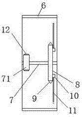
[0017] refer to Figure 1-2 As shown, a new energy cutting equipment of the present invention includes a main lifting rod 1, and two sets of columns 2 are arranged in opposite directions on the right side of the main lifting lever 1, and each of the sets of sets of columns Iron rods 3 are inserted into the inside of 2, and a first bearing (not shown) for the rotation of the iron rods 3 is also provided inside each of the sleeve columns 2, and the two ends of each of the iron rods 3 are extended To the outside of the set column 2, each of the iron rods 3 extending to the outside of the set column 2 is provided with walking tires 301, and the top a...


PUM


Abstract

The invention discloses a new energy cutting device comprising a main lifting rod. Two sleeve columns are arranged at the bottom of the right side of the main lifting rod and are opposite from left to right. An iron rod is inserted into each sleeve column. A first bearing used for rotation of the corresponding iron rod is further arranged in each sleeve column. The two ends of each iron rod both extend out of the corresponding sleeve column. The two ends, extending out of the corresponding sleeve column, of each iron rod are both provided with walking tires. An electric rotation machine is fixedly arranged on the top of the center of the main lifting rod. A storage battery driving the electric rotation machine to rotate is fixedly arranged on the top on the right side of the main lifting rod through a rack rod. A protective cover is fixedly arranged at the bottom of the left side of the main lifting rod. A second bearing is arranged at the left end of the main lifting rod. The new energy cutting device is simple in structure, low in cost and suitable for application and popularization, and cutting operation is easy and convenient.

Description

technical field [0001] The invention relates to the field of cutting machines, in particular to new energy cutting equipment. Background technique [0002] In the process of cutting the workpiece, a cutting machine is usually used for cutting. The traditional cutting machine drives the cutting blade to rotate at high speed through the electric rotary machine to cut the workpiece. When the outer surface of the workpiece is covered with dust or other impurities, it is necessary to clean the outer surface of the workpiece. The surface is first cleaned and then cut, so the operation steps are cumbersome, and the impurities on the outer surface of the workpiece cannot be cleaned and cut at the same time. Contents of the invention [0003] The technical problem to be solved by the present invention is to provide a new energy cutting device, which can solve the above-mentioned problems in the prior art. [0004] In order to solve the above problems, the present invention adopts ...

Claims


Application Information

Patent Timeline
Patent Type & Authority Applications(China)
IPC IPC(8): B28D1/24B28D7/02
CPCB28D1/24B28D7/02
Inventor 孟苏
Owner 南京首勤特种材料有限公司
Learn More