
Special stack mold injection molding machine for template opposite-opening mold moving middle injection

An injection molding machine and template technology, which is applied in the field of special injection molding machines for stack molds, can solve the problems of increasing manufacturing difficulty, low work efficiency, affecting action time, etc., and achieves the effects of improving action stability, improving work efficiency, and improving production efficiency.

Pending Publication Date: 2017-12-22
CHENGDU LIANYU PRECISION MACHINERY
View PDF0 Cites 1 Cited by
  • Summary
  • Abstract
  • Description
  • Claims
  • Application Information

AI Technical Summary

Problems solved by technology

In this way, when the mold is opened, a closing device is required to prevent material leakage, which increases the difficulty of manufacturing, and there is always a risk of material leakage, which affects the reliability of use
Moreover, when the mold is locked, there must be an additional contact force to ensure the sealing between the fixed cold half mold and the hot half mold, which will offset part of the clamping force and affect the consistency of the clamping force on both sides of the mold. Larger clamping force to ensure smooth molding, poor equipment reliability
[0005] (2) The brake structure is a very important mechanism in the injection molding machine. It is the key to the mold clamping step in the injection molding process. It directly affects the quality of the injection molded product and the injection efficiency. The existing brake structure can only be linked in pairs , and there are two brake cylinders to push separately, the brake and the mold opening are operated separately, and the four-point linkage cannot be realized, which will cause the brake to not be tightened or opened at the same time when it moves, affecting the action time and lower work efficiency
[0006] (3) In the existing stack mold injection molding machine, the cold half mold on one side is fixed on the fixed template of the injection molding machine, and the injection mechanism injects from the fixed side, which has a complex structure and low production efficiency. At the same time, the existing When the stack mold injection molding machine performs the mold opening and closing movement, the moving part always moves in one direction, the frame of the injection molding machine will be subject to a greater impact, and the service life of the injection molding machine is low. The improvement on the basis of the machine, the two moving molds always move relative to each other, the forces cancel each other out, the impact force will not be transmitted to the frame, and the machine runs faster and more smoothly
[0007] (4) In the existing stack injection molding machine, the cold half-mold on one side is fixed on the fixed template of the injection molding machine, and the injection mechanism injects from the fixed side, which occupies the space of the ejector device, so the traditional The ejector device (used to take out the molded plastic products) of the stack injection molding machine needs to be integrated on the mold, which makes the structure of the mold complex and makes some products unable to be produced by stack molding

Method used


Image

  • Special stack mold injection molding machine for template opposite-opening mold moving middle injection
  • Special stack mold injection molding machine for template opposite-opening mold moving middle injection
  • Special stack mold injection molding machine for template opposite-opening mold moving middle injection

Examples


Embodiment Construction

[0035] The technical solution of the present invention will be further described in detail below in conjunction with the accompanying drawings, but the protection scope of the present invention is not limited to the following description.

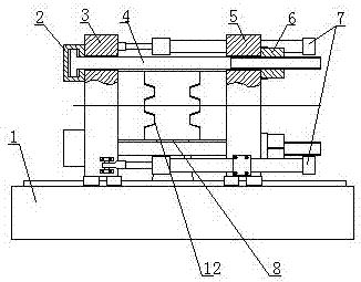
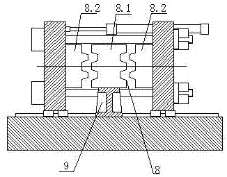
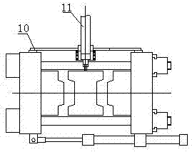
[0036] Such as figure 1 , figure 2 As shown in the figure, a special injection molding machine for stack molds with templates separated and moved in the middle of the mold includes a frame 1 and a mold 8. It also includes a pressurized oil cylinder group, a pressurized template 3, a brake template 5, a brake mechanism 6, Die transfer cylinder 7, mold base 9 and injection mechanism 11;

[0037] The booster template 3 and the brake template 5 are vertically installed on the frame 1, the booster cylinder group is composed of a plurality of booster cylinders 2, the booster cylinder 2 is fixed on the booster template 3, and the brake mechanism 6 is fixed on the brake On the template 5, the piston rod 4 of the booster cylinder 2 extends throug...


PUM


Abstract

The invention discloses a special stack mold injection molding machine for template opposite-opening mold moving middle injection. The special stack mold injection molding machine comprises a rack (1) and a mold (8) and further comprises a pressurizing oil cylinder set, a pressurizing template (3), a band-type brake template (5), a band-type brake mechanism (6), a mold moving oil cylinder (7), a mold base (9) and an injection mechanism (11). A pressurizing oil cylinder (2) achieves mold locking through the band-type brake mechanism (6). The mold moving oil cylinder (7) drives the pressurizing template (3) and the band-type brake template (5) to do the linear mold opening and closing movement on the rack (1), and a mold moving synchronous mechanism (10) is arranged between the pressurizing template (3) and the band-type brake template (5). The pressurizing template (3) and the band-type brake template (5) synchronously act through the mold moving synchronous mechanism (10). The special stack mold injection molding machine has the beneficial effects that material leakage risks happening during mold opening are avoided, an equipment structure is simplified, the equipment reliability is improved, and the equipment running stable degree is improved.

Description

technical field [0001] The invention relates to a special injection molding machine for a stack mold with templates separated and moved in the middle of a mold, and belongs to the technical field of mold injection molding machines. Background technique [0002] Injection molding machine is also known as injection molding machine or injection machine. It is the main molding equipment for making thermoplastics or thermosetting plastics into various shapes of plastic products using plastic molding molds. Divided into vertical, horizontal, all-electric. The injection molding machine heats the plastic, applies high pressure to the molten plastic, and makes it shoot out to fill the mold cavity. The working principle of the injection molding machine is similar to the syringe used for injection. It uses the thrust of the screw (or plunger) to inject the plastic that has been plasticized into the molten state (that is, the viscous flow state) into the closed cavity. The process of...

Claims


Application Information

Patent Timeline
Patent Type & Authority Applications(China)
IPC IPC(8): B29C45/12B29C45/66B29C45/40B29C45/17
CPCB29C45/12B29C45/17B29C45/4005B29C45/66
Inventor 张元海陈斌
Owner CHENGDU LIANYU PRECISION MACHINERY
Learn More