
Multi-connecting-rod suspension frame and vehicle assembly thereof

A multi-link and assembly technology, applied in the direction of suspension, elastic suspension, vehicle spring, etc., can solve the problems of large space occupied by multi-link suspension, unsuitable for cars with low chassis, complex structure, etc., to achieve Optimizing chassis cost, simple structure, and reducing the effect of car body inclination

Pending Publication Date: 2017-12-22
ZHEJIANG YINGLUN AUTOMOBILE CO LTD +2
View PDF0 Cites 7 Cited by
  • Summary
  • Abstract
  • Description
  • Claims
  • Application Information

AI Technical Summary

Problems solved by technology

[0003] However, since the multi-link suspension has many links and the structure is relatively complicated, the space occupied by the multi-link suspension in the height direction is relatively large, and it is not suitable for cars with low chassis.

Method used


Image

  • Multi-connecting-rod suspension frame and vehicle assembly thereof
  • Multi-connecting-rod suspension frame and vehicle assembly thereof
  • Multi-connecting-rod suspension frame and vehicle assembly thereof

Examples


Embodiment 1

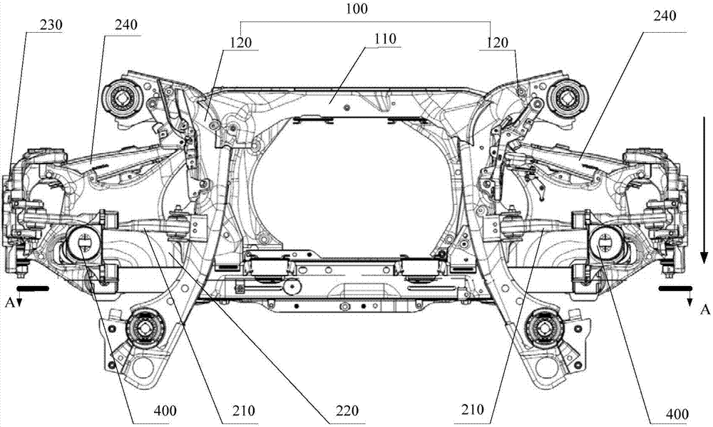
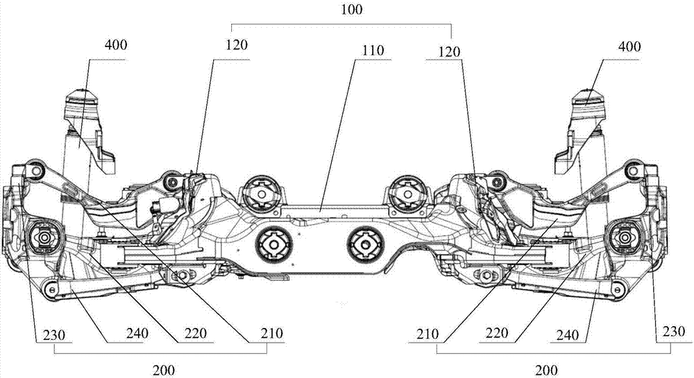
[0037] Such as figure 1 , figure 2 and image 3 As shown, the multi-link suspension provided by this embodiment includes: a leaf spring 300, a subframe 100, and two sets of link assemblies 200; two sets of link assemblies 200 are respectively arranged on both sides of the subframe 100; The vehicle frame 100 , the leaf spring 300 and the two sets of connecting rod assemblies 200 are arranged sequentially from top to bottom, and the leaf spring 300 connects the two sets of connecting rod assemblies 200 . Wherein, there are various installation points for the leaf spring 300, the subframe 100, and the two sets of connecting rod assemblies 200. As a preferred embodiment, the leaf spring 300 includes two upper installation points 310 and two lower installation points 320; The two upper mounting points 310 are connected to the bottom surface of the sub-frame 100 , and the two lower mounting points 320 are respectively connected to the two sets of connecting rod assemblies 200 . ...

Embodiment 2

[0052] The vehicle assembly provided in this embodiment includes: a vehicle body, a motor assembly for providing kinetic energy for the rear wheels of the vehicle body, and the multi-link suspension provided in Embodiment 1. The vehicle body is arranged on the multi-link suspension The upper end of the subframe 100 and the rear wheel of the car body are connected with the link assembly 200 of the multi-link suspension; the motor assembly is arranged on the subframe 100, and the motor assembly is connected with the rear wheel.

[0053] Specifically, when the subframe 100 includes the middle part 110 and two connecting parts 120, the motor assembly is arranged at the through hole of the middle part 110, and mounting points are arranged on both sides of the upper end of each connecting part 120, through The installation point is connected to the bottom of the car body, so that the multi-link suspension and the installed motor assembly have sufficient support and strength, and the ...


PUM


Abstract

The invention relates to the technical field of chassis, in particular to a multi-connecting-rod suspension frame and a vehicle assembly thereof. The multi-connecting-rod suspension frame comprises a plate spring, a subsidiary vehicle frame and two sets of connecting rod components; the two sets of connecting rod components are arranged at the two sides of the subsidiary vehicle frame respectively; the subsidiary vehicle frame, the spring plate and the two sets of connecting rod components are arranged from top to bottom in sequence, and the plate spring is connected with the two sets of the connecting rod components. The multi-connecting-rod suspension frame solves the technical problem that too much space is occupied in the height direction when too many connecting rods exist.

Description

technical field [0001] The invention relates to the technical field of chassis, in particular to a multi-link suspension and its vehicle assembly. Background technique [0002] Suspension is a very important system in a car nowadays. It connects the wheels and the car body in a certain way, and transmits the force and moment between the wheels and the car body, eases the impact, dampens the vibration, and controls the movement of the wheels. Regularity, to ensure the comfort and maneuverability of the car. Among them, the multi-link suspension is a set of suspension mechanisms that connect the wheels to the car body through various link configurations. It can better decouple the longitudinal force, lateral force and vertical force, which can not only improve the riding Comfort, and at the same time, it can well guarantee the requirements of handling performance. Therefore, multi-link suspension is becoming more and more popular and used. [0003] However, since the multi-...

Claims


Application Information

Patent Timeline
IPC IPC(8): B60G11/02B60G3/20
CPCB60G3/20B60G11/02B60G2204/14B60G2200/184B60G2202/11
Inventor 窦德海季红丽李明一
Owner ZHEJIANG YINGLUN AUTOMOBILE CO LTD
Learn More