Thrust bearing
A thrust bearing and axial displacement technology, applied in the field of thrust bearings, can solve problems such as stuck and unable to open, scrapped mechanism, difficult machine tools, etc.
- Summary
- Abstract
- Description
- Claims
- Application Information
AI Technical Summary
Problems solved by technology
Method used
Image

Examples
Embodiment 1
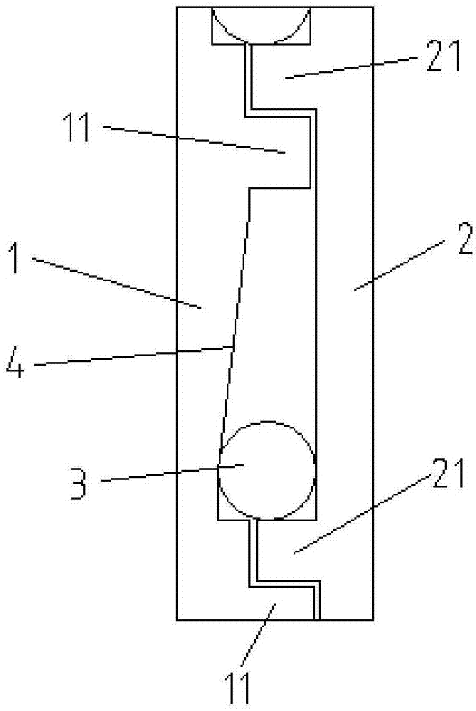
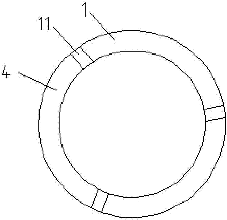
[0028] figure 1 Schematic diagram of the structure of the thrust bearing provided in Embodiment 1 of the present invention; figure 2 A schematic structural diagram of the upper cover provided in Embodiment 1 of the present invention; as Figure 1-Figure 2 As shown, the thrust bearing provided by Embodiment 1 of the present invention includes an upper sleeve 1, a lower sleeve 2 and a rolling element 3, the upper sleeve 1 and the lower sleeve 2 are connected in rotation in opposite directions, and the upper sleeve 1 is ring-mounted with The first stop tooth 11, the second stop tooth 21 is installed on the ring of the lower sleeve 2, the second stop tooth 21 is opposite to the first stop tooth 11, and is adjacent to the first stop tooth 11. The surface of the upper sleeve 1 between the limit teeth 11 is a slope 4, and the rolling element 3 is installed on the slope 4;
[0029] When the upper sleeve 1 and the lower sleeve 2 rotate in opposite directions, the second stop teeth 2...
Embodiment 2
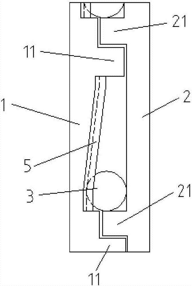
[0040] image 3 Schematic diagram of the structure of the thrust bearing provided in Embodiment 2 of the present invention; Figure 4 The structural schematic diagram of the upper sleeve provided for the second embodiment of the present invention; as Figure 3-Figure 4 As shown, the thrust bearing provided by Embodiment 2 of the present invention includes an upper sleeve 1, a lower sleeve 2 and a rolling element 3, the upper sleeve 1 and the lower sleeve 2 are connected in rotation in opposite directions, and the upper sleeve 1 is ring-mounted with The first stop tooth 11, the second stop tooth 21 is installed on the ring of the lower sleeve 2, the second stop tooth 21 is opposite to the first stop tooth 11, and is adjacent to the first stop tooth 11. The surface of the upper sleeve 1 between the limit teeth 11 is an inclined track 5, and the rolling body 3 is installed on the inclined track 5;
[0041] When the upper sleeve 1 and the lower sleeve 2 rotate in opposite direct...
Embodiment 3
[0052] The thrust bearing provided in Embodiment 3 is a further improvement on the thrust bearing provided in Embodiment 1. In Embodiment 1 and figure 1 , figure 2On the basis of , the thrust bearing provided in the third embodiment includes an upper sleeve 1, a lower sleeve 2 and a rolling element 3, the upper sleeve 1 and the lower sleeve 2 are connected in rotation in opposite directions, and the upper sleeve 1 is ring-mounted with The first stop tooth 11, the second stop tooth 21 is installed on the ring of the lower sleeve 2, the second stop tooth 21 is opposite to the first stop tooth 11, and is adjacent to the first stop tooth 11. The surface of the upper sleeve 1 between the limit teeth 11 is a slope 4, and the rolling element 3 is installed on the slope 4;
[0053] When the upper sleeve 1 and the lower sleeve 2 rotate in opposite directions, the second stop teeth 21 on the lower sleeve 2 drive the rolling elements 3 to move along the slope 4, so that the upper sleev...
PUM
 Abstract
Description
Claims
Application Information
 - R&D
- Intellectual Property
- Life Sciences
- Materials
- Tech Scout
- Unparalleled Data Quality
- Higher Quality Content
- 60% Fewer Hallucinations
Browse by: Latest US Patents, China's latest patents, Technical Efficacy Thesaurus, Application Domain, Technology Topic, Popular Technical Reports.
© 2025 PatSnap. All rights reserved.Legal|Privacy policy|Modern Slavery Act Transparency Statement|Sitemap|About US| Contact US: help@patsnap.com