Contact net tension monitoring device

A monitoring device and catenary technology, applied in tension measurement, measuring device, force/torque/work measuring instrument, etc., can solve the problems of inability to monitor the tension change of the catenary system in real time, unable to reflect the real-time dynamic situation of the catenary system, etc. Achieve the effect of improving sand resistance, increasing hardness, and facilitating unified analysis of data

Pending Publication Date: 2017-12-22
CHINA RAILWAY FIRST SURVEY & DESIGN INST GRP +1
View PDF5 Cites 1 Cited by
  • Summary
  • Abstract
  • Description
  • Claims
  • Application Information

AI Technical Summary

Problems solved by technology

Among them, the tension and stress of the catenary system are key parameters related to the stable, reliable and safe operation of the catenary system, and are directly related to the operating status and driving safety of the catenary system.

Method used


Image

  • Contact net tension monitoring device

Examples


Example Embodiment

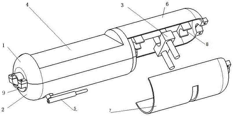
[0028] The present invention will be described in detail below in conjunction with specific embodiments.

[0029] The present invention relates to a catenary tension monitoring device. The device comprises a cylindrical shell, which is provided with a through hole along the axial direction, which is a through hole for a catenary clue (including: a load-bearing cable, an additional wire, etc.). The aperture can be adjusted adaptively according to the diameter of the catenary leads of different specifications. The shell is axially divided into two left and right sections. The left section of the housing includes a left upper housing 1 and a left lower housing 2, which are axially symmetrically butted up and down and fixed by screws; the right section of the housing includes a right upper housing 6 and a right lower housing 7, both axially Butt up and down symmetrically and fixed by screws. After being closed, it has a cylindrical cylindrical structure with good wind resistance. ...


PUM


Abstract

The present invention relates to a contact net tension monitoring device. The device comprises a cylindrical housing, the housing is divided into left and right sections along an axial direction, the right section is internally provided with a tension sensor and a temperature sensor, and the left section is internally provided with a communication circuit configured to output sensor monitoring data; the housing is provided with a through hole along the axial direction, the through hole is the via hole of the contact net cable, and the two ends of the through hole are provided with a clamp; and an antenna configured to monitor wireless transmission of data is arranged at the external portion of the left section of the housing. The contact net tension monitoring device is simple in structure, easy to use and substantial in technology effect, can be widely applied to occasions of contact net cable product design online monitoring to satisfy field environment work requirement of a contact net system, realize real-time monitoring of tension (stress) and temperature of the contact net and provide reliable, accurate and comprehensive monitoring data.

Description

technical field [0001] The invention relates to the technical field of electrified railway catenary monitoring, in particular to a catenary tension monitoring device. Background technique [0002] The electrified railway catenary is arranged in the open air along the railway line, and the line is long and there is no backup. With the rapid development of electrified railways, especially the expansion of the scale of high-speed electrified railway network, the railway department has put forward higher requirements for the operation safety of traction power supply system. Catenary system is an important part of high-speed railway power supply system. Its infrastructure Maintenance is faced with an urgent need to ensure safety, improve efficiency, and reduce costs. [0003] The catenary system is eroded by wind, frost, rain, snow and other natural environments all the year round, as well as the impact and vibration of the pantograph during high-speed operation. Its mechanical ...

Claims


Application Information

Patent Timeline
IPC IPC(8): G01L5/04G01K13/00G01K1/02
CPCG01K1/024G01K13/00G01L5/04G01L5/047
Inventor 张学武王争鸣肖卫民聂晶鑫张珹田升平章一洲鲁凡冯志民王玉环赵玮金光鲍君怡杨艺
Owner CHINA RAILWAY FIRST SURVEY & DESIGN INST GRP
Why Eureka
Try Eureka