Speed reducer and washing machine with speed reducer

A technology of a reducer and a washing machine, applied in the field of washing machines, can solve problems such as speed difference, and achieve the effect of improving the washing effect

Active Publication Date: 2017-12-26
QINGDAO HAIER WASHING MASCH CO LTD +1
View PDF7 Cites 15 Cited by
  • Summary
  • Abstract
  • Description
  • Claims
  • Application Information

AI Technical Summary

Problems solved by technology

[0005] In order to solve the above-mentioned problems in the prior art, that is, in order to solve the problem that the pulsator and the agitator of the pulsator washing machine cannot form a speed difference when rotating, the present invention provides a speed reducer, which includes a housing, A first planetary gear assembly, a second planetary gear assembly, an input shaft, a first output shaft, and a second output shaft; both the first planetary gear assembly and the second planetary gear assembly are disposed within the housing, and the The first planetary gear assembly is drivingly connected to the second planetary gear assembly; the first output shaft and the second output shaft are both arranged on one side of the housing, and are respectively connected to the first planetary gear The assembly is connected, and the second output shaft is sleeved on the first output shaft; the input shaft is arranged on the other side of the housing, and is connected with the second planetary gear assembly; the The input shaft can drive the first output shaft and the second output shaft to rotate in the same direction through the first planetary gear assembly and the second planetary gear assembly

Method used


Image

  • Speed reducer and washing machine with speed reducer
  • Speed reducer and washing machine with speed reducer
  • Speed reducer and washing machine with speed reducer

Examples


Embodiment Construction

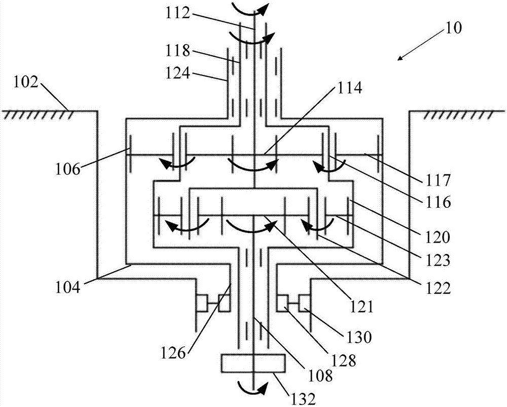
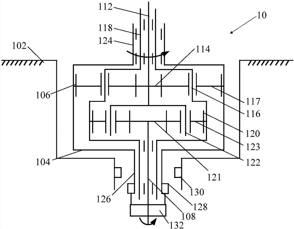
[0025] First of all, those skilled in the art should understand that these implementations are only used to explain the technical principles of the present invention, and are not intended to limit the protection scope of the present invention. Those skilled in the art can make adjustments as needed to adapt to specific application occasions. For example, although the speed reducer in this specification is used in a pulsator washing machine, the principle of the speed reducer of the present invention is that the first input shaft passes through the first planetary gear assembly and the second planetary gear assembly to make the first output shaft and the second output shaft follow the design. Rotate in the same direction at a given speed ratio. Therefore, the speed reducer of the present invention is not only applicable to the wave-wheel washing machine, but also applicable to other similar mechanisms, and such changes do not depart from the principle and scope of the present i...


PUM


Abstract

The invention relates to the technical field of home appliances, in particular to a speed reducer and a washing machine with the speed reducer. According to the technical aim, the problem is solved that in the prior art, an impeller and a stirrer of an impeller washing machine cannot generate speed difference in rotation. The invention provides the speed reducer. The speed reducer comprises a shell, a first planet wheel component, a second planet wheel component, an input shaft, a first output shaft and a second output shaft; the first planet wheel component and the second planet wheel component are arranged in the shell, and the first planet wheel component is connected with the second planet wheel component in a driving mode; the first output shaft and the second output shaft are arranged on one side of the shell and connected with the first planet wheel component respectively, and the second output shaft is arranged on the first output shaft in a sleeving mode; the output shaft is arranged on the other side of the shell and connected with the second planet wheel component; the input shaft can drive the first output shaft and the second output shaft to rotate in the same direction according to the preset speed ratio through the first planet wheel component and the second planet wheel component.

Description

technical field [0001] The invention relates to the technical field of home appliances, in particular to a speed reducer and a washing machine using the speed reducer. Background technique [0002] When the traditional pulsator washing machine is in the washing state, the pulsator drives the clothes and water in the pulsator washing machine to make directional rotation, and the purpose of washing clothes is realized during the directional rotation of the clothes and water. In contrast, when the traditional pulsator washing machine is in the dehydration state, the inner tub drives the clothes in the pulsator washing machine to rotate in a directional manner, and the purpose of drying is achieved during the rotation of the clothes. Although the working mode of the traditional pulsator washing machine can basically meet the purpose of washing and drying clothes, however, as users have higher and higher requirements for pulsator washing machines, the traditional pulsator washing...

Claims


Application Information

Patent Timeline
Patent Type & Authority Applications(China)
IPC IPC(8): D06F37/40
CPCD06F37/40
Inventor 田云张刚金傅晓东田云龙庄仲凯唐斌
Owner QINGDAO HAIER WASHING MASCH CO LTD
Why Eureka
Try Eureka