Supercharge Your Innovation With Domain-Expert AI Agents!

Valve spool displacement measuring test bed

A valve core displacement and test bench technology, which is applied in measuring devices, radio wave measurement systems, electromagnetic wave re-radiation and other directions, can solve the problem that high-speed switching valves cannot measure valve core displacement, etc., to improve market competitiveness, simple structure, Production cost reduction effect

Active Publication Date: 2017-12-26
TIANJIN TRINOVA AUTOMOTIVE TECH CO LTD
View PDF5 Cites 9 Cited by
  • Summary
  • Abstract
  • Description
  • Claims
  • Application Information

AI Technical Summary

Problems solved by technology

[0004] An object of the present invention is to provide a valve core displacement measurement test bench to solve the technical problem in the prior art that the valve core displacement cannot be measured for high-speed switching valves

Method used


Image

  • Valve spool displacement measuring test bed
  • Valve spool displacement measuring test bed
  • Valve spool displacement measuring test bed

Examples


Embodiment 1

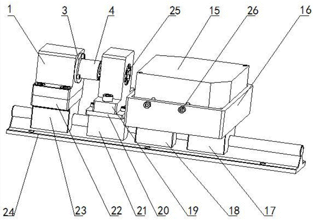
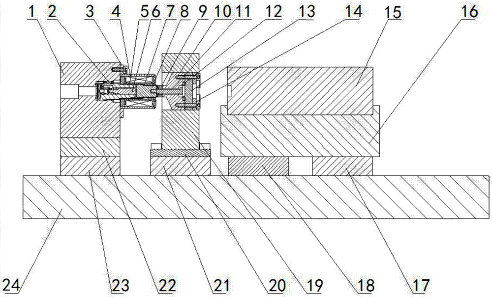
[0037] Such as Figure 1-4 As shown, the valve core displacement measurement test bench provided in this embodiment includes a linear guide rail 24, a valve seat 1, a first sliding part 21, a second sliding part 23, a third sliding part, a flange 3, an electromagnet coil 4, Sealing chamber 25, support 19, transition ring 9, laser displacement sensor 15 and mounting seat 16;

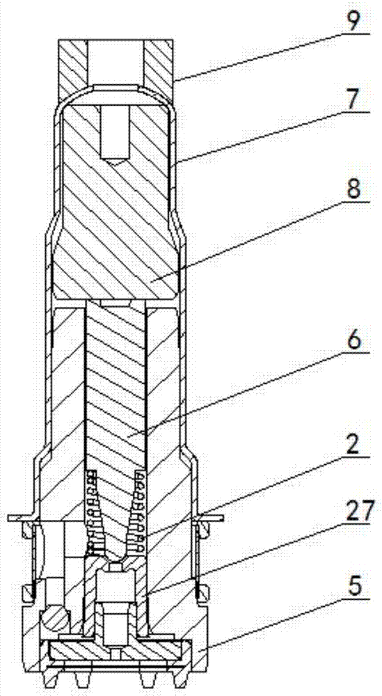
[0038] Such as Figure 1-2 As shown, the first sliding part 21, the second sliding part 23 and the third sliding part are sequentially slidably connected with the linear guide rail 24, the valve seat 1 is mounted on the first sliding part 21, and the valve The seat 1 is provided with an installation cavity, the first end of the switch valve is arranged in the installation cavity, the second end of the switch valve is provided with a through hole, and the moving iron 8 of the switch valve is provided with a connection hole , and the electromagnet coil 4 is fixed on the valve seat 1 through the flange 3, ...


PUM


Abstract

The invention provides a valve spool displacement measuring test bed which comprises a linear guide rail, a valve seat, a first sliding portion, a second sliding portion, a third sliding portion, a flange, an electromagnet coil, a sealing bin, a support, a transition ring, a laser displacement sensor and a mounting seat. The valve seat is mounted on the first sliding portion, the sealing bin is arranged on the support, the mounting seat is arranged on the third sliding portion, the laser displacement sensor is arranged on the mounting seat, a first end of a measuring rod can penetrate a sealing cover and a through hole and is fixedly connected with a connecting hole, so that the first end of the measuring rod is fixedly connected with a moving iron of a switching valve, the transition ring is welded with a plunger tube of the switching valve and the sealing cover, a transparent plate fixes a sealing ring into a groove of the sealing cover through a pressing plate and a bolt, a second end of the measuring rod is sealed in high-pressure oil, the laser displacement sensor can irradiate the second end of the measuring rod through the transparent plate and then reflect laser to a receiving port of the laser displacement sensor, and displacement of the measuring rod is calculated by the aid of optical reflection theory, namely, displacement of a valve spool is calculated.

Description

technical field [0001] The invention relates to the technical field of a switching valve spool measuring mechanism, in particular to a spool displacement measuring test bench. Background technique [0002] At present, in daily life, people often use displacement sensors to measure the tiny displacement of objects, and displacement sensors are divided into contact type and non-contact type. One end of the contact sensor is fixed, and the other end is connected to the measured object, so that the displacement of the measured object can be measured. The non-contact type does not need to be directly connected to the measured object, and the displacement is measured through electromagnetic or optical signal transmission. [0003] However, for high-speed switching valves, the spool is sealed inside the magnetic isolation tube, which cannot be connected with traditional contact displacement sensors, and displacement measurement cannot be performed. For the non-contact magnetostric...

Claims


Application Information

Patent Timeline
IPC IPC(8): G01S17/08G01B11/02
CPCG01B11/02G01S17/08
Inventor 赵洵李亮方继根吴进军
Owner TIANJIN TRINOVA AUTOMOTIVE TECH CO LTD
Features
  • R&D
  • Intellectual Property
  • Life Sciences
  • Materials
  • Tech Scout
  • Unparalleled Data Quality
  • Higher Quality Content
  • 60% Fewer Hallucinations
Learn More