Method and device for removing noise in image

An image-in-noise technology, applied in the information field, can solve the problems of reduced performance and more time spent in the dictionary, and achieve the effect of reducing processing time, improving image quality, and saving computing resources.

Inactive Publication Date: 2017-12-26
NOKIA TECHNOLOGLES OY
3 Cites 8 Cited by

AI-Extracted Technical Summary

Problems solved by technology

However, the performance of this method will degrade if the dictionary does not ...

Abstract

A method and a device for removing noise in an image are disclosed in the invention. The method comprises the following steps: the image is decomposed into a high frequency part and a low frequency part, a feature matrix for the high frequency part is determined, each feature vector in the feature matrix represents an image block for each image block in the high frequency part, at least the feature matrix and a coefficient matrix are used for representing the feature matrix, and an optimal solution for the coefficient matrix is determined while a rank of at least the coefficient matrix is minimized; based on the optimal solution for the coefficient matrix, an image block corresponding to noise in the high frequency part is determined and then removed, and the high frequency part with the noise removed and the low frequency art are combined to obtain an image with the noise removed. Technical effects of the method and device disclosed in the invention are that computing resources can be saved, processing time can be reduced, and image quality can be improved.

Application Domain

Technology Topic

Coefficient matrixHigh frequency +6

Image

  • Method and device for removing noise in image
  • Method and device for removing noise in image
  • Method and device for removing noise in image

Examples

  • Experimental program(1)

Example Embodiment

[0029] The embodiments of the present disclosure are described below with reference to the drawings. In the following description, many specific details are set forth to enable those skilled in the art to understand and implement the present disclosure more comprehensively. However, it is obvious to those skilled in the art that the embodiments of the present disclosure can be implemented without some of these specific details. In addition, it should be understood that the present disclosure is not limited to the specific embodiments described. On the contrary, it may be considered to implement the embodiments of the present disclosure with any combination of the features and elements described below. Therefore, the following aspects, features, embodiments and advantages are for illustrative purposes only, and should not be regarded as elements or limitations of the claims, unless explicitly stated in the claims.
[0030] It should be noted that in some embodiments of the present disclosure, the embodiments of the present disclosure will be described in conjunction with removing rain lines in the image, but the embodiments of the present disclosure are not limited to removing rain lines in the image, but may It is suitable for removing any suitable noise components in the image. In addition, although the embodiments of the present disclosure are mainly introduced in the context of a single image below, it should be understood that the embodiments of the present disclosure can also be applied to videos. It should also be noted that the embodiments herein can be applied not only to processing non-real-time images or videos, but also to processing real-time images or videos. In addition, it should be noted that the images in this article can be color images or grayscale images.
[0031] Throughout the text, the same mark refers to the same element. As used herein, the words "data", "content", "information" and similar words are used interchangeably to refer to data that can be transmitted, received, and/or stored in accordance with embodiments of the present disclosure. Therefore, the use of any such words should not be considered as limiting the spirit and scope of the embodiments of the present disclosure.
[0032] In addition, as used herein, the term "circuit" refers to: (a) only hardware circuit implementation (for example, implementation in analog circuits and/or digital circuits); (b) circuits and computer program products (multiple ), the computer program product(s) include: software and/or firmware instructions stored on one or more computer-readable memories, and the combination works together to cause the device to execute one or more of the Function; and (c) a circuit (such as, for example, a microprocessor(s) or part of a microprocessor(s)) that requires software or firmware for operation, even if the software or firmware is not physically present. This definition of'circuitry' applies to all uses of this word herein (including in any claims). As a further example, as used herein, the term'circuitry' also includes: an implementation that includes one or more processors and/or part(s) thereof and is accompanied by software and/or firmware.
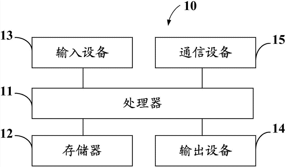
[0033] figure 1 A block diagram of a device (such as the electronic device 10) according to at least one example embodiment is shown. However, it should be understood that the electronic devices described herein and hereinafter are merely illustrative of electronic devices that can benefit from the embodiments of the present disclosure, and therefore should not be considered as limiting the scope of the present disclosure. Although the electronic device 10 is illustrated and will be described hereinafter for the purpose of example, other types of electronic devices may easily utilize the embodiments of the present disclosure. The electronic device 10 can be a portable digital assistant (PDA), mobile computer, desktop computer, smart TV, game device, portable computer, media player, camera, video recorder, mobile phone, global positioning system (GPS) device, smart glasses , Car navigation system, video surveillance system, smart phone, tablet computer, laptop computer, server, thin client, cloud computer, virtual computer, set-top box, computing device, distributed system and/or any other type of electronic system. The electronic device 10 can run any type of operating system, which includes but is not limited to Windows, Linux, UNIX, Android, iOS and their variants. Furthermore, in other example embodiments, the electronic device of at least one example embodiment does not need to be the entire electronic device, but may be a component or component group of the electronic device.
[0034] In addition, the electronic device 10 can easily utilize the embodiments of the present disclosure regardless of whether the electronic device is mobile or fixed. In this regard, even though the embodiments of the present disclosure can be described in conjunction with mobile applications, it should be understood that they can be used in conjunction with various other applications (for example, various other applications in addition to mobile applications, such as traffic monitoring applications). Embodiments of the present disclosure.
[0035] In at least one example embodiment, the electronic device 10 includes a processor 11 and a memory 12. The processor 11 may be any type of processor, controller, embedded controller, processor core, and/or the like. In at least one example embodiment, the processor 11 uses computer program code to cause the electronic device 10 to perform one or more actions. The memory 12 may include: volatile memory, such as volatile random access memory (RAM) (which contains a cache area for temporary storage of data), and/or other memory, for example, non-volatile memory, which It can be embedded and/or can be removable. Non-volatile memory may include: EEPROM, flash memory, and/or the like. The memory 12 can store any number of pieces of information, as well as data. The information and data may be used by the electronic device 10 to implement one or more functions of the electronic device 10, such as the functions described herein. In at least one example embodiment, the memory 12 includes computer program code. The memory and the computer program code are configured to work with the processor to cause the electronic device to perform one or more actions described herein.
[0036] The electronic device 10 may further include: a communication device 15. In at least one example embodiment, the communication device 15 includes an antenna (or multiple antennas), a wired connector, and/or the like, which are in operative communication with a transmitter and/or receiver. In at least one example embodiment, the processor 11 provides signals to the transmitter and/or receives signals from the receiver. The signal may include: signaling information according to the communication interface standard, user voice, received data, user-generated data, and/or the like. The communication device 15 can operate using one or more air interface standards, communication protocols, modulation types, and access types. As an illustration, the communication device 15 can operate according to the following protocols: the second generation (2G) wireless communication protocol IS-136 (Time Division Multiple Access (TDMA)), Global System for Mobile Communications (GSM), and IS-95 (Code Division Multiple Access (CDMA)), third-generation (3G) wireless communication protocols, such as Universal Mobile Telecommunication System (UMTS), CDMA2000, Wideband CDMA (WCDMA) and Time Division Synchronous CDMA (TD-SCDMA), and/or the first Four-generation (4G) wireless communication protocols, wireless networking protocols (such as 802.11), short-range wireless protocols (such as Bluetooth), and/or the like. The communication device 15 may operate in accordance with a wired protocol, such as Ethernet, digital subscriber line (DSL), asynchronous transfer mode (ATM), and/or the like.
[0037] The processor 11 may include components such as circuits for implementing audio, video, communication, navigation, logic functions, and/or the like, and for implementing embodiments of the present disclosure, including, for example, the functions described herein One or more of the functions. For example, the processor 11 may include components for performing various functions (including, for example, one or more functions described herein), such as a digital signal processor, a microprocessor, various analog-to-digital converters, and digital-to-digital converters. Analog converters, processing circuits and other support circuits. The electronic device 10 can perform control and signal processing functions. The processor 11 may include the function of encoding and interleaving messages and data before modulation and transmission. The processor 11 may also include an internal voice encoder, and may include an internal data modem. In addition, the processor 11 may include operating one or more software programs, the software programs may be stored in the memory, and the software programs may enable the processor 11 to implement at least one embodiment, such as one or more of the functions described herein. Multiple functions. For example, the processor 11 may operate a connectivity program, such as a conventional web browser. The connectivity program may allow the electronic device 10 to transmit and receive network content (such as location-based content and/or other web content) according to the following: for example, Transmission Control Protocol (TCP), Internet Protocol (IP), User Datagram Protocol (UDP) ), Internet Message Access Protocol (IMAP), Post Office Protocol (POP), Simple Mail Transfer Protocol (SMTP), Wireless Application Protocol (WAP), Hypertext Transfer Protocol (HTTP) and/or the like.
[0038] The electronic device 10 may include a user interface for providing output and/or receiving input. The electronic device 10 may include an output device 14. The output device 14 may include: audio output devices, such as ringers, earphones, speakers, and/or the like. The output device 14 may include a tactile output device, such as a vibration sensor, an electrically deformable surface, an electrically deformable structure, and/or the like. The output device 14 may include: a visual output device, such as a display, a lamp, and/or the like. The electronic device may include: an input device 13. The input device 13 may include: a light sensor, a proximity sensor, a microphone, a touch sensor, a force sensor, a button, a keypad, a motion sensor, a magnetic field sensor, a motion sensor, a camera, and/or the like. In embodiments that include a touch display, the touch display may be configured to receive input from single touch, multi touch, and/or the like. In such embodiments, the touch display and/or processor may determine the input based at least in part on orientation, movement, speed, contact area, and/or the like.
[0039] The electronic device 10 may include various touch displays, for example, the touch display is configured to enable various resistive, capacitive, infrared, strain gauge, surface wave, optical imaging, dispersive signal technology, acoustic pulse Recognition and/or other technologies of touch recognition and then provide signals indicating the location and other parameters associated with the touch. In addition, the touch display may be configured to receive an indication of input in the form of a touch event, and a touch event may be defined as the actual movement between the selected object (for example, a finger, stylus, stylus, or other pointing device) and the touch display Physical touch. The touch input may include any input detected by the touch display, which includes touch events that involve actual physical contact and touch events that do not involve physical contact but are detected by the touch display in other ways. The touch display is capable of receiving information related to the touch input and associated with the force applied to the touch screen. For example, the touch screen can distinguish between heavy press touch input and light press touch input. In at least one example embodiment, the display may display two-dimensional information, three-dimensional information, and/or the like.
[0040] The input device 13 may include a media capture element. The media capture element may be any member used to capture images, video, and/or audio for storage, display, or transmission. For example, in at least one example embodiment (where the media capture element is a camera module), the camera module may include a digital camera, which may form a digital image file from the captured image. Therefore, the camera module may include hardware (such as a lens or other optical component(s)) and/or software required to create a digital image from the captured image. Alternatively, the camera module may include: hardware only for viewing images, and the storage device of the electronic device 10 stores instructions for execution by the processor 11 in the form of software, the instructions for creating a digital image from the captured image . In at least one example embodiment, the camera module may further include: a processing element (such as a coprocessor) and an encoder and/or decoder, the processing element assists the processor 11 to process image data, and the encoder and/or decoder is used for Compress and/or decompress image data. The encoder and/or decoder may be based on a standard format (such as the Joint Photographic Experts Group (JPEG) standard format, the Moving Picture Experts Group (MPEG) standard format, the Video Coding Experts Group (VCEG) standard format or any other suitable standard format) Perform encoding and/or decoding.
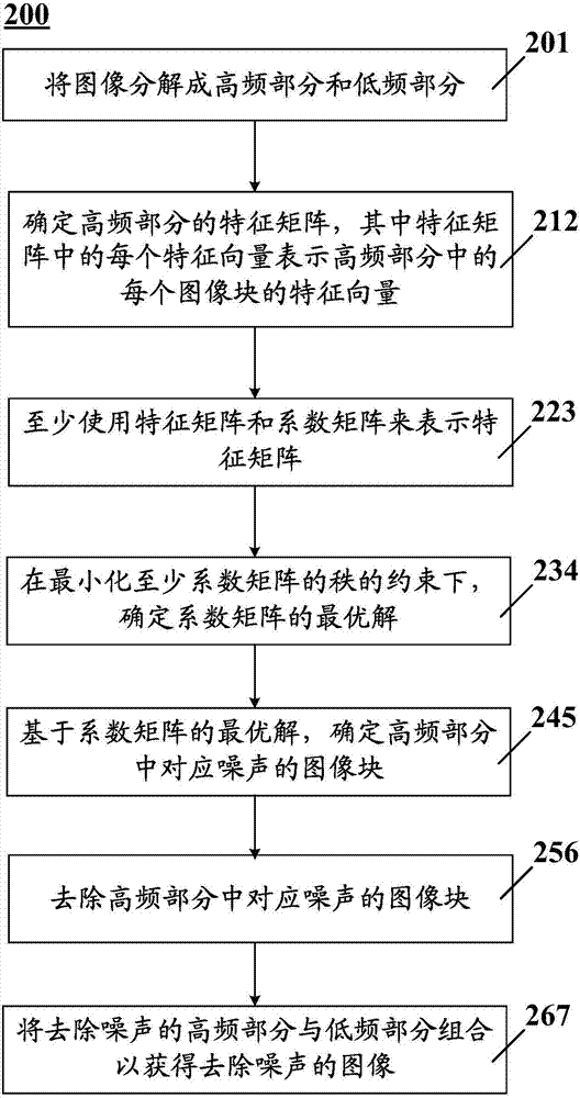
[0041] figure 2 Shows a flowchart of a method 200 for removing noise in an image according to an embodiment of the present disclosure. figure 1 The method 200 is executed at the device of the electronic device 10. Therefore, the electronic device 10 may provide components for implementing various parts of the method 200 and components for implementing other functions of the electronic device 10.
[0042] The noise in the image can refer to any noise that affects the quality of the image. For example, the noise in the image can be objects in bad weather, such as rain, snow, smoke, fog, dust, sand, etc.; it can be noise caused by imaging equipment, such as noise caused by a large number of particles on the camera lens; it can be Noise caused by on-site imaging conditions, such as taking images or videos through glass covered with a large amount of particulate matter, or any other noise. As an example, in rainy and snowy weather, the image acquired by a digital camera often contains many rain or snow lines. In this case, if the rain or snow lines in the image are not removed, the performance of the vision system will be greatly affected, for example, objects in the image (for example, license plate numbers, etc.) cannot be accurately recognized. In addition, driving in rainy and foggy weather, low visibility and falling raindrops will interfere with human eyes, seriously affecting the naked eye observation, and easily cause traffic accidents. Reports on sports events in snowy weather, falling snow will also cause some interference to the narrator's reports, and also affect the viewing experience of users watching sports events. Therefore, it is necessary to remove noise (such as rain lines or snow lines) in the image to improve the performance of the visual system and the user experience. In the following, the various embodiments are mainly described in the context of removing rain lines in an image, but the embodiments herein can be applied to remove any suitable noise in an image and are not limited to removing rain lines in an image.
[0043] As in figure 2 As shown in, the method 200 starts at block 201. In block 201, the image is decomposed into a high frequency part and a low frequency part. The image may be an image pre-stored in a memory in the electronic device 10, or an image captured in real time by, for example, an image sensor, or an image acquired from a local location or a network location. For example, in a traffic vision system, vehicle images and the like can be acquired through a digital camera arranged on the road.
[0044] The image can include a color image or a grayscale image. Color images may include images of any color model, for example, RGB color model, HSL color model, CMYK color model, and so on. Image formats include but are not limited to: bmp, jpg, jpeg, tiff, gif, pcx, tga, exif, fpx, svg, psd, cdr, pcd, dxf, ufo, eps, ai, raw or other suitable formats.
[0045] In block 201, any existing or any suitable image decomposition method developed in the future can be used to decompose the image into high frequency parts. HF And low frequency part I LF , Most of the basic information will remain in the low frequency part I LF Middle and high frequency part I HF Contains noise components (such as rain components). For example, the image can be decomposed into high-frequency parts through any smoothing filter with smoothing effect. HF And low frequency part I LF. High frequency part I HF And low frequency part I LF Generally have the same size as the image.
[0046] In one embodiment, the image is decomposed into a high-frequency part and a low-frequency part by the bilateral filter described in the following documents or its variants: L. Itti, C. Koch, and E. Niebur, "A model of saliency-based visual attention for Rapid scene analysis, "IEEE Trans. Pattern Anal. Mach. Intell., vol. 20, no. 11, pp. 1254-1259, Nov 1998, the entire content of this document is incorporated herein by reference.
[0047] In another embodiment, the image is decomposed into a high-frequency part and a low-frequency part by the guided filter described in the following document or its variants: Kaiming He, Jian Sun, Xiaoou Tang, "Guided Image Filtering," IEEE Trans.Pattern Anal.Mach.Intell.35(6):1397-1409(2013), the entire content of this document is incorporated herein by reference.
[0048] In one embodiment, the smoothing parameter of the smoothing filter is adjusted according to the intensity of the noise. As an example, there are generally two parameters of a smoothing filter such as a bilateral filter (which may be referred to as a smoothing parameter in this document): one is the variance in the spatial domain, and the other is the variance in the intensity domain. Usually the value of the former is larger than the latter, about an order of magnitude larger. As an example, if the intensity of noise (such as rain lines) is high, the two smoothing parameter values ​​can be increased to achieve the effect of suppressing rain lines in the low-frequency space; if the rain lines are small, the two balance parameter values ​​can be reduced to avoid Make the image too smooth to destroy the detailed information of the useful image.
[0049] After obtaining the high frequency part, the method 200 may proceed to block 212. In block 212, the feature matrix of the high frequency part is determined, where each feature vector in the feature matrix represents the feature vector of each image block in the high frequency part. In block 212, any existing or future technical means can be used to determine the feature matrix of the high frequency part.
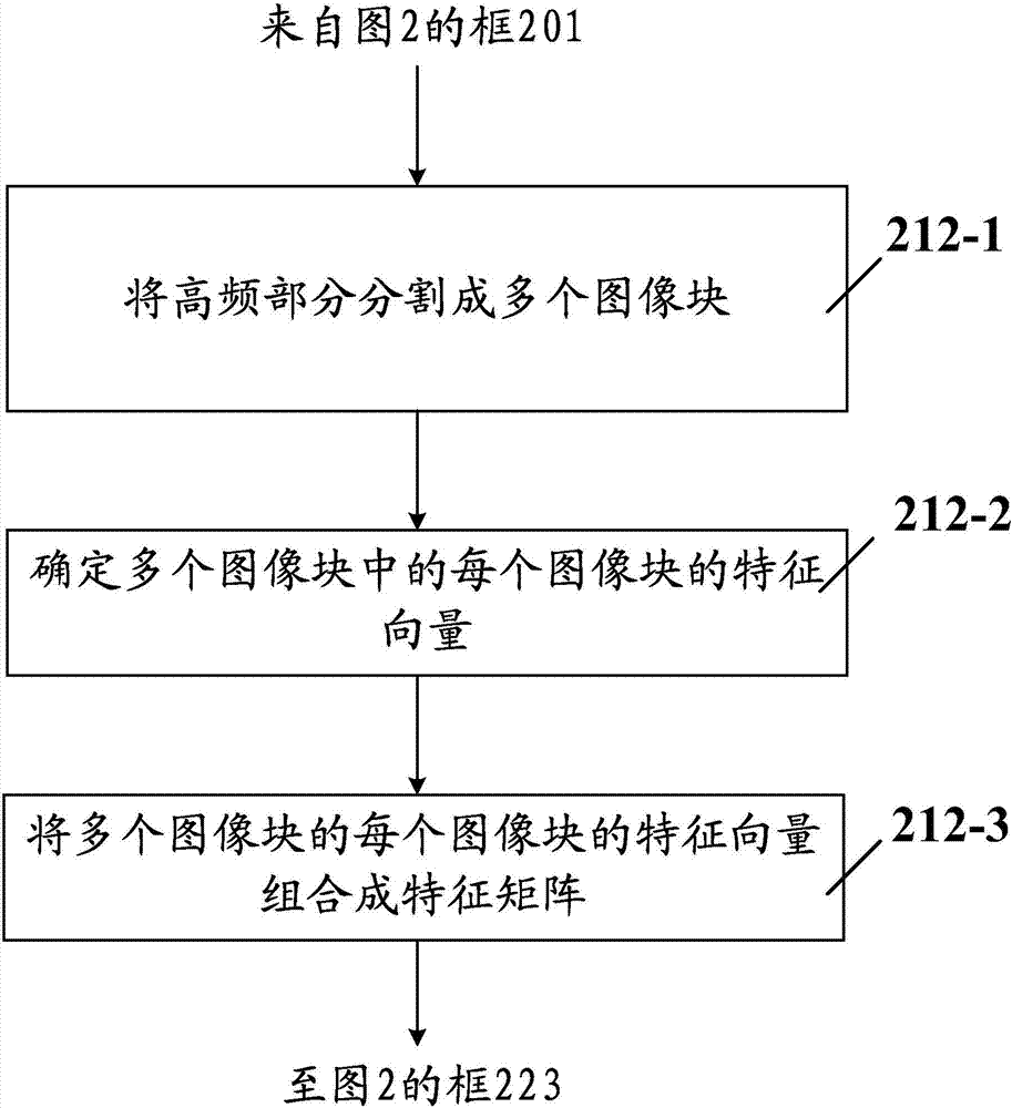
[0050] in image 3 In the illustrated embodiment, determining the feature matrix of the high-frequency part includes: block 212-1, dividing the high-frequency part into multiple image patches; block 212-2, determining each of the multiple image blocks The feature vector of each image block; and block 212-3, combining the feature vector of each image block of the multiple image blocks into a feature matrix. Specifically, the high frequency part I HF It can be divided into multiple image blocks, such as multiple image blocks of the same size. In an embodiment, the size of the image block may be 16×16 pixels or other suitable sizes. In other embodiments, the size of each image block in the multiple image blocks may also be different. Intuitively, the most salient features of the appearance of rain can be extracted through “image gradient”, where “image gradient” is a technique known to those skilled in the art. Therefore, HOG (Histogram of Oriented Gradient) descriptors can be used to describe the characteristics of each image block. The basic idea of ​​HOG is that when the corresponding gradient or edge position cannot be accurately known, the local intensity gradient or edge direction can better describe the appearance and shape of the local object. In this embodiment, each image block can be evenly divided into a plurality of cells. As an example, if the size of an image block is 16×16 and it is divided into 2×2 mutually non-overlapping units, then the size of each unit is 8×8. Then, for each unit, the local 1-D (1-D) gradient direction or edge orientation on the pixels of the unit can be accumulated. The combined histogram descriptor of all cells in each image block forms the HOG representation of that image block. Therefore, by extracting the directional gradient histogram descriptor for each image block to determine the feature vector of each image block in the multiple image blocks, each image block can obtain a feature vector x, the features of all image blocks of the image The vectors are combined into a feature matrix X as input to the subsequent processing of the method 200. As an example, suppose the image is divided into 4 image blocks, if x i Represents the feature vector of an image block (assuming it is a column vector) and its dimension is n, then the feature matrix X can be [x 1 ,x 2 ,x 3 ,x 4 ], that is, each column of the feature matrix X is an feature vector, the feature matrix X is composed of 4 feature vectors, and the size of the feature matrix X is n×4. In other embodiments, the feature matrix X can also be formed in any other suitable form, for example, the position of the column vector in the feature matrix can be changed.
[0051] In one embodiment, dividing the high frequency part into a plurality of image blocks includes: dividing the high frequency part into a plurality of overlapping image blocks; or dividing the high frequency part into a plurality of non-overlapping image blocks. Depending on the situation, different segmentation schemes can be used. For example, dividing the high-frequency part into multiple non-overlapping image blocks can increase the processing speed, while dividing the high-frequency part into multiple overlapping image blocks can improve performance, but consumes more resources and increases processing time. Therefore, in different scenarios, the embodiments of the present disclosure may use different segmentation schemes. For example, in the case of high processing delay requirements, in the case of relatively insufficient computing resources, or in the case of high real-time requirements, a non-overlapping segmentation scheme can be used. In the case of high performance requirements, or in the case of relatively sufficient processing resources, or in the case of low real-time requirements, an overlapping segmentation scheme can be used.
[0052] After obtaining the feature matrix of the image, the method 200 proceeds to block 223. In block 223, at least the feature matrix and the coefficient matrix are used to represent the feature matrix. For example, the feature matrix can be represented by the following formula:
[0053] X=XZ+E (1)
[0054] Where Z is the coefficient matrix used to represent the characteristic matrix X, E is the residual matrix, where Z and E are unknown quantities, and X is the known quantity.
[0055] In block 234, the optimal solution of the coefficient matrix is ​​determined under the constraint of minimizing at least the rank of the coefficient matrix. For example, in block 234, the following equation can be solved:
[0056]
[0057] Among them, the rank of the feature matrix X is expressed as rank(X), and λ is a coefficient, which can balance rank(X) and ||E|| 2. If the coefficient matrix Z is a good representation of the feature matrix X, the rank of the feature matrix X will be very small and the error matrix E and its L2 norm ||E|| 2 It is also very small, so in equation (2), the characteristic matrix can be expressed as X=XZ. However, because of the rank (X) of the characteristic matrix X, it is difficult to solve equation (2). In order to deal with this problem, the nuclear norm ||Z|| * Can be used to replace rank(X). Therefore, equation (2) can become the following equation:
[0058]
[0059] Equation (3) is a standard low-rank representation problem and standard algorithms can be used to solve it.
[0060] In another embodiment, as described above, if the coefficient matrix Z is a good representation of the characteristic matrix X, then the L2 norm of the error matrix E ||E|| 2 Is also very small, so λ||E|| 2 Is also very small, so the term λ||E|| can also be omitted 2 , So equation (3) can also become the following equation:
[0061]
[0062] Using equation (4) to solve the coefficient matrix Z will further reduce computing resource requirements, reduce computing time, and further reduce processing delays, which is beneficial to applications that require real-time processing.
[0063] It should be noted that, in the existing classic dictionary learning methods, the dictionary is obtained by applying complex learning algorithms to the high-frequency part. On the one hand, calculating the dictionary takes time and effort. On the other hand, since the rain component and the non-rain component cannot be completely distinguished, the learned dictionary may not be satisfactory, and thus the image produced according to this method is also unsatisfactory. In the embodiment of the present disclosure, the data sample (ie, the feature matrix of the image) itself is used as a dictionary, that is, in the embodiment of the present disclosure, no learning algorithm is needed to obtain the dictionary, because the dictionary is the input image (ie , The feature matrix of the image) itself. Therefore, compared with the prior art, the data sample itself is used as a dictionary, so that the dictionary is the simplest dictionary. In this way, computing resources can be saved, processing time can be reduced, and shortcomings in the method based on dictionary learning can be avoided. In addition, another difference from the existing dictionary-based learning method is that the embodiments of the present disclosure apply low-order constraints to the coefficient matrix used to represent the data sample (for example, the feature matrix of the data sample).
[0064] After the optimal solution of the coefficient matrix is ​​obtained, the method 200 proceeds to block 245. In block 245, based on the optimal solution of the coefficient matrix, the image block corresponding to the noise in the high frequency part is determined. For example, the feature of each vector in the coefficient matrix can be analyzed, and whether it corresponds to the feature of noise can be determined according to the feature. If it corresponds to the feature of noise, the feature vector corresponding to the vector can be determined, so that the image block corresponding to the feature vector in the high frequency part is determined to be a noise image block. In other embodiments, any suitable existing or future technical means may be used to determine the image block corresponding to the noise in the high-frequency part based on the optimal solution of the coefficient matrix.
[0065] in Figure 4 In an embodiment shown, based on the optimal solution of the coefficient matrix, determining the image block corresponding to the noise in the high-frequency part includes: block 245-1, performing a clustering algorithm on the optimal solution of the coefficient matrix In order to divide the vector in the coefficient matrix into two vector groups; block 245-2, determine the vector group corresponding to the noise in the two vector groups; and block 245-3, determine the corresponding noise in the high-frequency part based on the vector group corresponding to the noise Image block. Specifically, any applicable clustering algorithm, such as the k-means clustering algorithm, can be applied to the coefficient matrix Z to divide the vector in the coefficient matrix Z into two vector groups, such as the noise (for example, rain line component) vector Groups and non-noise (e.g. geometric components) vector groups. Then, determine the vector group corresponding to the noise in the two vector groups. For example, you can combine each vector into a vector, and then calculate the variance of the resulting vector. Generally speaking, non-noise components (for example, geometric components) have complex information, so the variance of the composite vector belonging to the non-noise components should be greater than the variance of the composite vector belonging to the noise components. In other words, a vector group with a large variance corresponds to a non-rain component, and a vector group with a small variance corresponds to a rain component. In addition, the characteristics of each vector of the coefficient matrix can also be analyzed. For example, the eigenvectors belonging to the rain component generally have the same variance. Therefore, the variance of the vectors in the coefficient matrix can be counted, and the vectors belonging to a certain variance interval can be classified as the vector corresponding to the noise. Group, classify other vectors into corresponding non-noise vector groups. Then, the image block corresponding to the noise in the high frequency part is determined based on the feature vector in the feature matrix corresponding to the vector group of the corresponding noise.
[0066] In block 256, the image blocks corresponding to noise in the high frequency part are removed. For example, the elements in the image block corresponding to the noise in the high frequency part can be zeroed out, so as to obtain the high frequency part from which the noise is removed.
[0067] In block 267, the noise-removed high-frequency part and the low-frequency part are combined to obtain a noise-removed image. For example, the noise-removed high-frequency part and the low-frequency part can be added to obtain a noise-removed image.
[0068] Figure 5 A schematic diagram showing a flowchart of removing rain components in an input image according to an example embodiment. Reference Figure 5 ,in Figure 5 The images shown in represent input images, output images, and intermediate images. At 501, a rain image is input. At 502, the rain image is filtered through a bilateral filter to be decomposed into a high frequency part and a low frequency part, where the high frequency part contains rain components. At 503, perform patch extraction on the high-frequency part, determine the feature vector of each patch, and combine the feature vectors of all patches in the high-frequency part into a feature matrix. In this embodiment, the feature vector of each patch is used as the feature matrix Then use the feature matrix as a dictionary, at least use the feature matrix and the coefficient matrix to represent the feature matrix. In 504, the optimal solution of the coefficient matrix is ​​determined under the constraint of minimizing at least the rank of the coefficient matrix. In 505, perform a clustering algorithm on the determined coefficient matrix to divide the vectors in the coefficient matrix into two vector groups, determine the vector group corresponding to the noise in the two vector groups, and then determine the high value based on the vector group corresponding to the noise The image block corresponding to the noise in the frequency part, that is, the high frequency part can be divided into non-rain part and rain part. In 506, the non-rain part in the high frequency part and the low frequency part are combined to obtain a noise-removed image. In 507, an image without rain is output.
[0069] Based on the same inventive concept as the above method, the present disclosure also provides a device for removing noise in an image. The device may include means for performing the steps of the above method. Regarding the same parts as the foregoing embodiment, their description is appropriately omitted.
[0070] In one embodiment, the device includes a component for decomposing an image into a high frequency part and a low frequency part; a component for determining a feature matrix of the high frequency part, wherein each feature vector in the feature matrix represents The feature vector of each image block in the high-frequency part; a component used to represent the feature matrix using at least the feature matrix and coefficient matrix; used to minimize at least the rank of the coefficient matrix under the constraint , A component for determining the optimal solution of the coefficient matrix; a component for determining an image block corresponding to noise in the high-frequency part based on the optimal solution of the coefficient matrix; a component for removing the corresponding noise in the high-frequency part A member of a noisy image block; and a member for combining a noise-removed high-frequency part with the low-frequency part to obtain a noise-removed image.
[0071] In one embodiment, the means for decomposing the image into a high frequency part and a low frequency part includes: a means for decomposing the image into a high frequency part and a low frequency part through a smoothing filter.
[0072] In an embodiment, the smoothing parameter of the smoothing filter is adjusted according to the intensity of the noise.
[0073] In an embodiment, the means for determining the feature matrix of the high-frequency part includes: means for dividing the high-frequency part into a plurality of image blocks; and means for determining each of the plurality of image blocks. And a member for combining the feature vector of each image block of the plurality of image blocks into a feature matrix.
[0074] In one embodiment, the means for dividing the high frequency part into a plurality of image blocks includes: means for dividing the high frequency part into a plurality of overlapping image blocks; or a means for dividing the high frequency part into a plurality of overlapping image blocks; The frequency part is divided into multiple non-overlapping image blocks.
[0075] In one embodiment, the device further includes means for determining the feature vector of each image block of the plurality of image blocks by extracting the directional gradient histogram descriptor for each image block.
[0076] In at least one embodiment, the means for determining image blocks corresponding to noise in the high-frequency part based on the optimal solution of the coefficient matrix includes: performing clustering on the optimal solution of the coefficient matrix The algorithm is used to divide the vector in the coefficient matrix into two vector groups; a component for determining the vector group corresponding to the noise in the two vector groups; and a component for determining the vector group based on the corresponding noise The component of the image block corresponding to the noise in the high-frequency part.
[0077] In at least one embodiment, the noise includes rain or snow.
[0078] Image 6 The results of removing rain in an image according to an embodiment of the present disclosure and other methods are shown. Other methods include the method of the following reference (in this disclosure, it is referred to as method 2): LWKang, CWLin, and YHFu, "Automatic single-image-based rainstreaks removal via image decomposition," IEEE Trans.on ImageProcessing, vol.21, no.4, pp.1742-1755, 2012, and the method of the following references (in this disclosure, it is referred to as method 3): DA Huang, LWKang, YCFWang, and CWLin ,"Selflearning based image decomposition with applications to single image denoising,"IEEE Trans.Multimedia,vol.16,no.1,pp.83-93,2014. Image 6 (a) represents the original image with rain; Image 6 (b) Represent the result of Method 2; Image 6 (c) Represent the result of Method 3; and Image 6 (d) shows the result of the method of the present disclosure. From Image 6 It can be seen that the method according to the embodiments of the present disclosure has the best rain removal effect, for example Image 6 (d) In the rectangular frame marked in (d), the method of the present disclosure removes a lot of rain and maintains better image details.
[0079] Table 1 shows the image quality evaluation results. In Table 1, four image quality evaluation methods are used: FSIM (Feature-similarity), SR_SIM (Spectral Residual based Similarity), VSI (Visual Saliency Induced Index), and VIF (Visual Information Fidelity). The range of these values ​​is between 0 and 1. The larger the value, the better the performance.
[0080] Table 1
[0081]
[0082] It can be seen from Table 1 that the method according to the embodiment of the present disclosure has a larger value than the method 2. This means that the method according to the embodiment of the present disclosure can better restore the image.
[0083] Note that any of the components of the above-described apparatus can be implemented as hardware, software modules, or a combination thereof. In the case of software modules, they can be included on a tangible computer-readable and recordable storage medium. All software modules (or any subset thereof) can be on the same medium, or each software module can be on a different medium. The software module can run on the hardware processor. Different software modules running on the hardware processor are used to execute the method steps.
[0084] In addition, an aspect of the present disclosure may use software running on a general-purpose computer or workstation. Such an implementation may use, for example, a processor, a memory, and an input/output interface formed by a display and a keyboard, for example. The term "processor" as used herein is intended to include any processing device, such as a processor including a CPU (central processing unit) and/or other forms of processing circuits. In addition, the term "processor" may refer to more than one processor. The term "memory" is intended to include memory associated with a processor or CPU, such as RAM (random access memory), ROM (read only memory), fixed memory (for example, hard disk), removable storage device (for example, magnetic disk), Flash memory, etc. Processors, memory and input/output interfaces (such as displays and keyboards) can be interconnected via a bus, for example.
[0085] Therefore, computer software (which contains instructions and codes for performing the methods of the present disclosure as described herein) can be stored in one or more of the associated memory devices, and when ready to be used At that time, it is partially or fully loaded (for example, loaded into RAM) and executed by the CPU. Such software may include but is not limited to firmware, resident software, microcode, and the like. Computer software can be computer software written in any programming language, and can be in the form of source code, object code, or intermediate code between the source code and the object code, such as partially compiled form, or in any other form The desired form.
[0086] The embodiments of the present disclosure may take the form of a computer program product contained in a computer readable medium having computer readable program code contained thereon. In addition, any combination of computer readable media can be used. The computer-readable medium may be a computer-readable signal medium or a computer-readable storage medium. The computer-readable storage medium may be, but is not limited to, an electric, magnetic, electromagnetic, optical, or other storage medium, and may be a removable medium or a medium fixedly installed in devices and equipment. Non-limiting examples of such computer readable media are RAM, ROM, hard disk, optical disk, optical fiber, etc. The computer-readable medium may be, for example, a tangible medium, for example, a tangible storage medium.
[0087] The words used herein are only for the purpose of describing specific embodiments, and are not intended to limit the embodiments. As used herein, the singular forms "a", "an" and "the" mean that the plural forms are also included, unless the context clearly dictates otherwise. It should also be understood that when used herein, the words "including", "having", "including" and/or "containing" refer to the presence of the stated features, numbers, steps, operations, elements and/or components, but It does not exclude the presence or addition of one or more other features, numbers, steps, operations, elements, components and/or combinations thereof.
[0088] It should also be noted that in some alternative implementations, the illustrated functions/acts may occur out of the order illustrated in the drawings. If necessary, different functions described in the present disclosure may be performed in a different order and/or concurrently with each other. In addition, if necessary, one or more of the above functions may be optional or may be combined.
[0089] Although the embodiments of the present disclosure have been described above with reference to the accompanying drawings, those skilled in the art can understand that the above description is only an example, not a limitation of the present disclosure. Various modifications and variations can be made to the embodiments of the present disclosure while still falling within the spirit and scope of the present disclosure, and the scope of the present disclosure is only determined by the appended claims.

PUM

no PUM

Description & Claims & Application Information

We can also present the details of the Description, Claims and Application information to help users get a comprehensive understanding of the technical details of the patent, such as background art, summary of invention, brief description of drawings, description of embodiments, and other original content. On the other hand, users can also determine the specific scope of protection of the technology through the list of claims; as well as understand the changes in the life cycle of the technology with the presentation of the patent timeline. Login to view more.

Similar technology patents

Classification and recommendation of technical efficacy words

  • Save computing resources
  • Reduce processing time
Why Eureka
Try Eureka