Sample position calibration method and calibration device

A calibration method and a technology of a sample carrying device, which are applied in the field of sample position calibration methods and devices, can solve problems such as difficult positioning at the same position, and achieve the effect of strong versatility and wide application range

Pending Publication Date: 2017-12-26
FOCUS E BEAM TECH BEIJING CO LTD
View PDF0 Cites 15 Cited by
  • Summary
  • Abstract
  • Description
  • Claims
  • Application Information

AI Technical Summary

Problems solved by technology

[0003] Based on the scanning electron microscope and its detection method, when the sample is first transmitted from the optical field of view to the scanning electr

Method used


Image

  • Sample position calibration method and calibration device
  • Sample position calibration method and calibration device
  • Sample position calibration method and calibration device

Examples


Embodiment Construction

[0039] The present invention will be described below in conjunction with the accompanying drawings and embodiments.

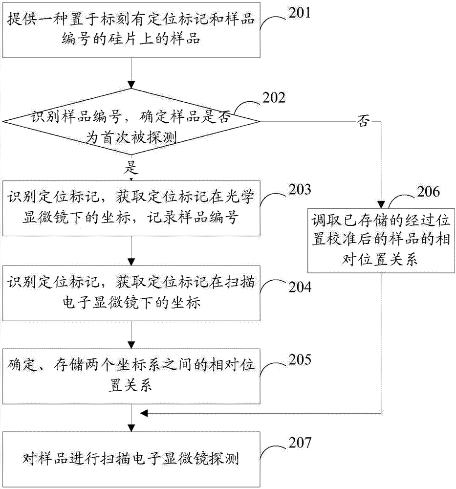
[0040] An embodiment of the present invention provides a sample position calibration method, such as figure 1 As shown, the method includes:

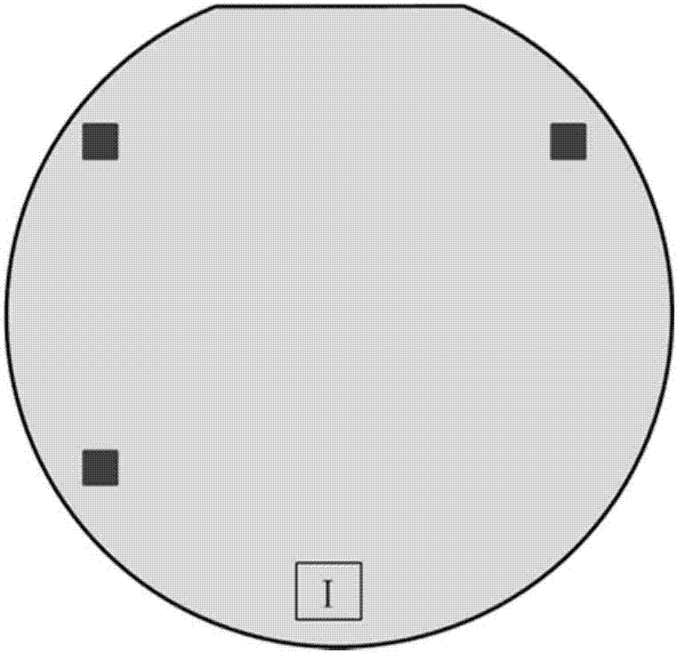
[0041] Step 101: loading the sample carrying device with the sample into the field of view of the optical microscope; positioning marks are set on the sample carrying device;

[0042] Taking an image of the sample carrying device at a first magnification with an optical microscope, identifying the positioning mark in the image and obtaining the first coordinates of the positioning mark under the optical microscope;

[0043] Step 102: Load the sample carrying device into the field of view of the scanning electron microscope, use the scanning electron microscope to take an image of the sample carrying device at a second magnification, identify the positioning mark in the image and obtain the scanning electron microscope i...


PUM


Abstract

This paper provides a sample position calibration method and device, the method comprising: loading a sample carrying device with a sample into the field of view of an optical microscope; positioning marks are provided on the sample carrying device; using an optical microscope to form a sample carrying device Image of the first magnification, identify the positioning mark in the image and obtain the first coordinates of the positioning mark under the optical microscope; load the sample carrying device into the field of view of the scanning electron microscope, and use the scanning electron microscope to zoom in on the sample carrying device for the second time Multiple image, identify the positioning mark in the image and obtain the second coordinate of the positioning mark under the scanning electron microscope; according to the first coordinate and the second coordinate, determine the coordinate system corresponding to the optical microscope and the coordinate system corresponding to the scanning electron microscope. Relative positional relationship; locate the sample based on the relative positional relationship. This application can solve the problem of inaccurate positioning of the sample when switching between the optical system and the scanning electron microscope.

Description

technical field [0001] The invention relates to the technical field of scanning electron microscopes, in particular to a sample position calibration method and device. Background technique [0002] Traditional scanning electron microscopy is widely used in sample microscopic morphology detection and comprehensive analysis. However, due to its high magnification and small field of view, it is difficult to locate the position of the sample to be measured. At present, a scanning electron microscope combined with an optical microscope system and its detection method have been proposed. The method includes: using an optical microscope to optically detect the sample to obtain an overall navigation map of the surface of the sample to be tested; based on the navigation map , located at the specified position of the sample to be tested, and a scanning electron microscope is used for higher-resolution detection. The above-mentioned entire detection process is automatically completed...

Claims


Application Information

Patent Timeline
IPC IPC(8): H01J37/20
CPCH01J37/20
Inventor 何伟李帅王瑞平
Owner FOCUS E BEAM TECH BEIJING CO LTD
Why Eureka
Try Eureka