
Teflon bar forming device

A polytetrafluoroethylene rod and forming device technology, which is applied in the field of polytetrafluoroethylene rod forming devices, can solve the problems of high cost, complex structure, low production efficiency, etc., and achieve the reduction of work burden, simple and reasonable design, and high work efficiency. high effect

Pending Publication Date: 2017-12-29
ZHEJIANG SONGHUA NEW MATERIAL CO LTD
View PDF7 Cites 2 Cited by
  • Summary
  • Abstract
  • Description
  • Claims
  • Application Information

AI Technical Summary

Problems solved by technology

However, there are still many deficiencies in the current market for PTFE rod forming devices. For example, the forming device and the feeding device are not easy to connect, and the connection is prone to material leakage, etc., the structure is complex and expensive, the production efficiency is low, and the forming is cooled. After the bar is not easy to take out, etc.

Method used


Image

  • Teflon bar forming device
  • Teflon bar forming device
  • Teflon bar forming device

Examples


Embodiment 1

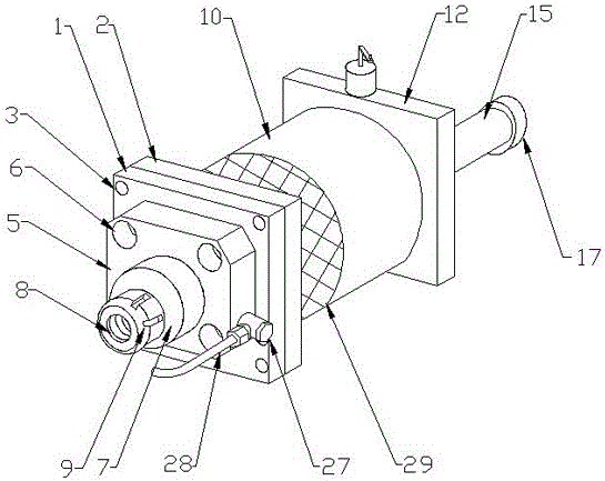
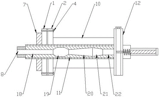
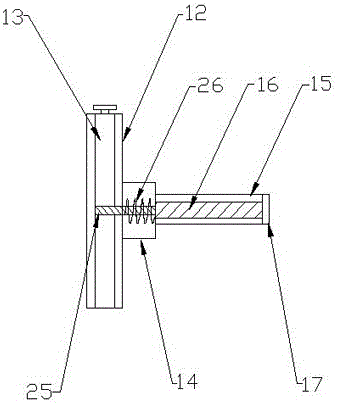
[0020] Such as Figure 1-4 As shown, the present invention provides a polytetrafluoroethylene rod forming device, comprising a positioning step 1 and a flange 2, the positioning step 1 and the flange 2 are provided with bolt holes 3, and the bolts 4 pass through the bolt holes 3 Connect the positioning step 1 and the flange plate 2 together, the positioning step 1 is connected with a positioner 5, the positioner 5 is provided with a number of positioning holes 6, the positioner 5 is provided with a machine head 7, and the machine head 7 is provided with an output The feeding port 8 and the feeding port 8 are provided with several positioning grooves 9, the flange plate 2 is connected with a feeding tube 10, the inside of the feeding tube 10 is provided with a feeding channel 11, and the feeding tube 10 is connected with a mold plate 12, The inside of the mold plate 12 is provided with a rotating shaft 13, the mold plate 12 is connected with a shaft sleeve 14, the shaft sleeve ...


PUM


Abstract

The invention discloses a teflon bar forming device. The teflon bar forming device comprises a positioning step and a flange plate which are provided with bolt holes. Bolts penetrate the bolt holes to connect the positioning step with the flange plate together. The positioning step is connected with a positioning device provided with a plurality of positioning holes. A machine head is arranged on the positioning device and provided with a material conveying port. The material conveying port is provided with a plurality of positioning grooves. The flange plate is connected with a material conveying barrel. A material conveying channel is arranged in the material conveying barrel. The material conveying barrel is connected with a die plate. A rotation shaft is arranged in the die plate. The die plate is connected with a shaft sleeve connected with a bar forming pipe. An inner rod is arranged in the bar forming pipe and is of a hollow structure, and the bar forming pipe is connected with a plug. Through the arrangement of the positioning device and the multiple positioning grooves, the forming device and a material conveying device are firmly connected together, and the situation that connection of the forming device and a feeding device is not easy, and material leakage happens is avoided.

Description

technical field [0001] The invention relates to the field of mechanical manufacturing, in particular to a polytetrafluoroethylene rod forming device. Background technique [0002] PTFE rod is an unfilled PTFE resin suitable for processing various gaskets, seals and lubricating materials working in corrosive media, as well as electrical insulating parts used at various frequencies. (may contain recycled polytetrafluoroethylene resin) Rods formed by compression molding, paste extrusion or plunger extrusion. There are two types of PTFE rods: push rods and molded rods. Among known plastics, PTFE has the best chemical corrosion resistance and dielectric properties, and can be used at temperatures ranging from -180°C to +260°C. , and has the lowest coefficient of friction, mainly suitable for some long products and mechanical parts of non-standard specifications. [0003] Now on the market, PTFE rods are generally produced by extrusion molding. Extrusion molding is also called e...

Claims


Application Information

Patent Timeline
Patent Type & Authority Applications(China)
IPC IPC(8): B29C47/08B29C47/88
CPCB29C48/06B29C48/25B29C48/911
Inventor 杨成刚
Owner ZHEJIANG SONGHUA NEW MATERIAL CO LTD
Learn More