Compression Fitting

Inactive Publication Date: 2010-06-17
HOEV
View PDF18 Cites 2 Cited by
  • Summary
  • Abstract
  • Description
  • Claims
  • Application Information

AI Technical Summary

Benefits of technology

[0009]It is the object of the invention to provide a compression fitting which is suitable for use in connection with hard pipes, and is also capable of keeping tight at high media pressures.
[0010]This is achieved according to the invention by providing the cone ring with slits extending from the pointed end and inwardly to ensure resilience and hereby tight engagement with the cone of the reception member and the exterior of the pipe.
[0011]In this simple manner, an absolutely tight connection between the pipe and the fitting part is achieved entirely without the use of the so-called cutting rings, but s

Problems solved by technology

For these purposes, it not possible to use the known cutting fittings, which are known to be used e.g. for the joining of copper pipes, the reason being that cutting cannot be carried out in a hard steel pipe.
This results in the cutting of the front part of the cone ring down into the pipe.
Th

Method used


Image

  • Compression Fitting
  • Compression Fitting
  • Compression Fitting

Examples


Embodiment Construction

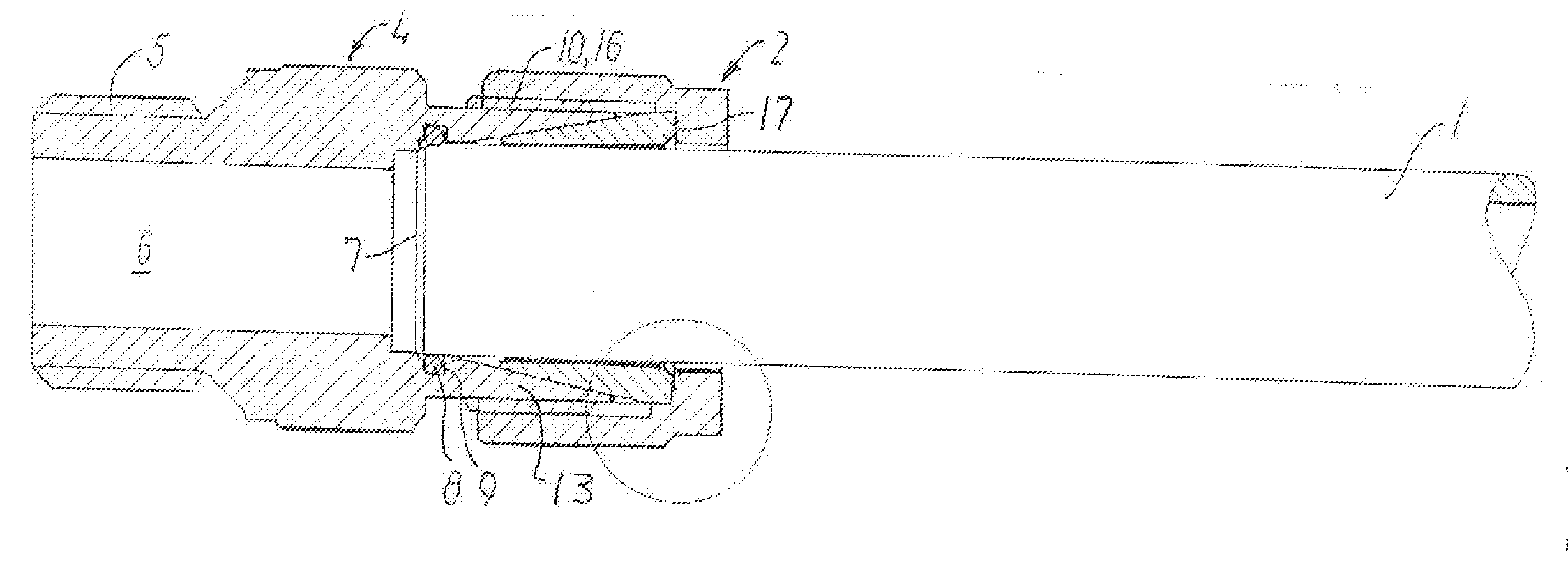
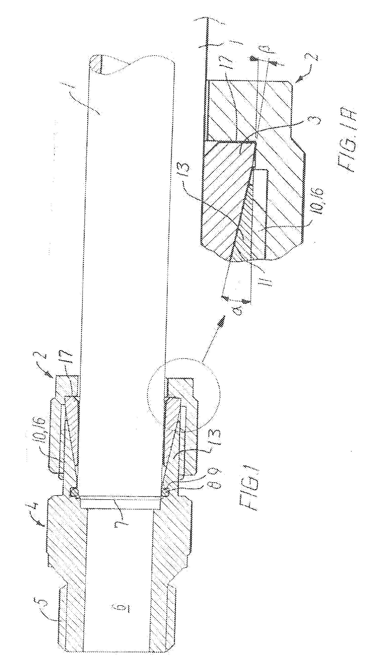
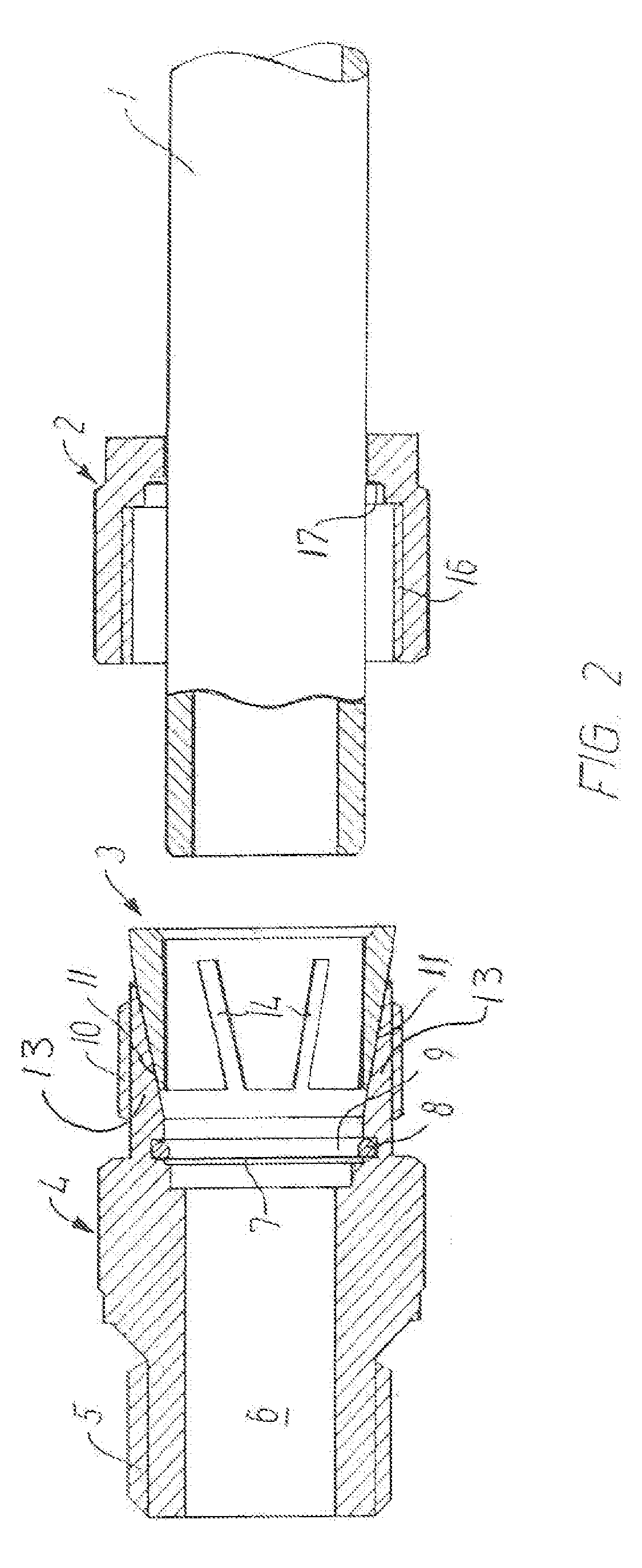
[0023]With reference to FIG. 2, the individual parts of a compression fitting according to the invention will be described.

[0024]To the left in the drawing, the fitting part 4 is shown in a sectional view, in the form of an assembly member having a through bore 6 and having a reception member 13 to the right in the drawing.

[0025]External threads 5 for the threaded mounting or other mounting of the fitting are shown at the outer, left end.

[0026]Outer threads 10 on to which the union unit 2 may be screwed, are shown externally on the reception member, since this nut has cooperating, internal threads 16.

[0027]Inside the part 4, there is an abutment 7 with which the pipe end 1 may be engaged at the mounting. In front of this abutment 7, there is a groove or channel 9 into which an O-ring 8 may be inserted, said ring just allowing the pipe 1 to slide through, thereby guiding it.

[0028]Furthermore, an internal cone face 11 extends in the reception member 13, into which a cone ring 3 may be...


PUM


Abstract

Joining of stainless steel pipes by means of a compression fitting requires a special configuration of it, since the known cutting fittings cannot be used with steel parts because of the hardness of the steel pipe. When a fitting according to the invention is configured with a reception member (4) and this is provided with an internally extending cone face (1) and a cone ring (3) having an externally extending, cooperating cone face and having slits (14, 16) in the cone ring (3), these parts may be tightened together by means of a union nut (2). Tightness is ensured, even at very high media pressures: in that the cone ring (3) is capable of adapting itself to the surface of the pipe (1) at the tightening-together.

Description

[0001]The invention relates to a compression fitting comprising a union nut and a cone ring adapted to be received in and screwed on to the fitting part around a pipe, wherein the reception member of the fitting part is provided with an internally extending cone, and wherein the cone ring is provided with an externally extending cone, said two cones having the same cone angle such that when the union nut is tightened on the fitting part, the cone ring will form a liquid-tight engagement with the reception part and the exterior of the pipe, and wherein the end member of the cone ring forms an engagement face with the inner bottom face of the union nut, and wherein the end portion of the cone ring forms a cone angle with the inner side of the union nut, said angle being smaller than the other cone angle of the cone ring.[0002]Fittings of this type are used for the joining of particularly stainless steel pipes.[0003]Stainless pipelines, pipes are used for many purposes, since this mate...

Claims


Application Information

Patent Timeline
IPC IPC(8): F16L55/00
CPCF16L19/065
Inventor HOVE, THOMAS
Owner HOEV
Why Eureka
Try Eureka