Papermaking drying cylinder

A papermaking dryer and drying cylinder technology, which is applied in papermaking, papermaking, textiles and papermaking, etc., can solve the problems of being unsuitable for high-speed drying cylinders and affecting the dynamic balance of high-speed drying cylinders, and achieves simple structure, easy processing, and easy realization. Effect

Inactive Publication Date: 2017-12-29
大冶市华锋纸业有限公司
View PDF0 Cites 0 Cited by
  • Summary
  • Abstract
  • Description
  • Claims
  • Application Information

AI Technical Summary

Problems solved by technology

[0003] Some people propose to add a spoiler rod on the inner wall of the drying cylinder and make it rotate with the drying cylinder. Since this structure will affect the dynamic balance of the high-speed drying cylinder, it is not suitable for high-speed drying cylinders.

Method used


Image

  • Papermaking drying cylinder

Examples


Embodiment

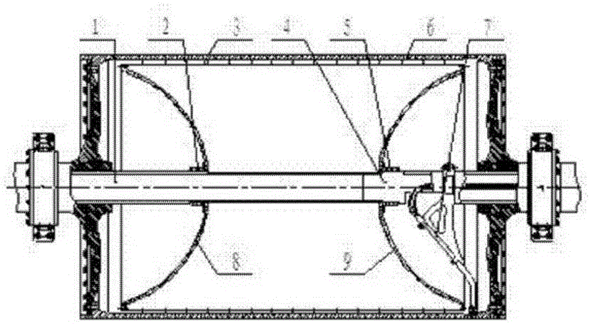
[0018] Embodiment, a kind of papermaking drying cylinder, set steam pipe 1, support pipe 4 and siphon pipe 7 inside, one end of support pipe 4 is a closed end and penetrates into steam pipe 1 and is axially connected with it, can block the steam pipe 1. The steam enters the support pipe 4; the drying cylinder 6 is provided with an inner cylinder 3, which is fixed on the steam pipe 1 and the support pipe 4, and the inner cylinder 3 is provided with evenly distributed steam injection holes. The two ends of the inner cylinder 3 are respectively provided with a left flange 2 and a right flange 5, and are respectively fixed on the steam pipe 1 and the support pipe 4 through the left flange 2 and the right flange 5, and the steam pipe 1 is provided with a shaft shoulder and The left flange 2 is coordinated for positioning, and the support tube 4 is provided with a shaft shoulder to coordinate with the right flange 5 for positioning. The siphon pipe 7 is connected with the support pi...


PUM


Abstract

A paper-making drying cylinder is provided with a steam pipe and a supporting pipe inside. The drying cylinder is provided with an inner cylinder, and the inner cylinder is provided with evenly distributed steam injection holes and is fixed on the steam pipe and the supporting pipe. In the present invention, an inner cylinder with steam injection holes is arranged in the drying cylinder and fixed on the steam pipe and the support pipe. The steam enters the inner cylinder from the steam pipe, flows out from the steam injection holes of the inner cylinder at high speed, and impacts on the inner wall of the drying cylinder. The condensed water ring layer makes it disturb and turbulent, which greatly reduces the heat transfer resistance of the condensed water ring layer, improves the heat transfer efficiency, and does not affect the dynamic balance of the high-speed drying cylinder. At the same time, the structure is simple and the parts Easy to process.

Description

technical field [0001] The invention relates to a drying cylinder, in particular to a high-speed papermaking drying cylinder. Background technique [0002] At present, the paper machines with multi-stage steam ventilation system generally have low thermal efficiency and high steam consumption in the drying section. For high-speed paper machines, the condensed water produced by the steam will form a stable water ring close to the inner wall of the dryer, reducing the turbulence of the condensed water, increasing the heat transfer resistance and reducing the heat transfer coefficient. That is, without special interference, the thermal resistance of a 1mm thick condensate ring in the dryer is approximately equal to the thermal resistance of a 15mm dryer cast iron shell. When the thickness of the condensate ring layer exceeds 2mm, the thermal resistance increases significantly. [0003] Someone proposed to add a spoiler rod on the inner wall of the drying cylinder and make it r...

Claims


Application Information

Patent Timeline
Patent Type & Authority Applications(China)
IPC IPC(8): D21F5/02
CPCD21F5/021D21F5/028
Inventor 柯雄彬
Owner 大冶市华锋纸业有限公司
Why Eureka
Try Eureka