Flat heat pipe

A flat plate heat pipe and plate body technology, applied in the field of heat transfer, can solve the problems of low thermal conductivity, increased liquid flow resistance, poor heat transfer performance, etc., and achieve the effect of excellent heat transfer performance and reduced flow resistance.

Pending Publication Date: 2017-07-14
TECHNICAL INST OF PHYSICS & CHEMISTRY - CHINESE ACAD OF SCI
View PDF9 Cites 10 Cited by
  • Summary
  • Abstract
  • Description
  • Claims
  • Application Information

AI Technical Summary

Problems solved by technology

Generally, the thermal conductivity of the capillary structure is low. When the thickness of the capillary structure is small, the temperature gradient on both sides of it is small, but the liquid flow resistance will become larger; when the capillary structure is thick, the liquid flow resistance decreases, but the heat transfer The thermal resistance becomes larger during the
And now many flat heat pipes conduct heat transfer in a gravity-assisted state (the heat source is on the bottom and the cold source is on the top). When working in the anti-gravity state, the heat transfer performance is poor. The force is increased, but at the same time the liquid flow resistance will become larger

Method used


Image

  • Flat heat pipe
  • Flat heat pipe
  • Flat heat pipe

Examples


Embodiment Construction

[0027] In order to facilitate the understanding of the present invention, the present invention will be described more fully below with reference to the associated drawings. Preferred embodiments of the invention are shown in the accompanying drawings. However, the present invention can be embodied in many different forms and is not limited to the embodiments described herein. On the contrary, these embodiments are provided to make the understanding of the disclosure of the present invention more thorough and comprehensive.

[0028] Unless otherwise defined, all technical and scientific terms used herein have the same meaning as commonly understood by one of ordinary skill in the technical field of the invention. The terms used herein in the description of the present invention are for the purpose of describing specific embodiments only, and are not intended to limit the present invention.

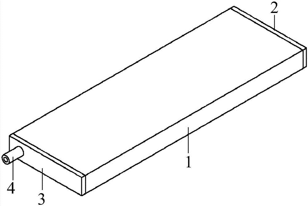
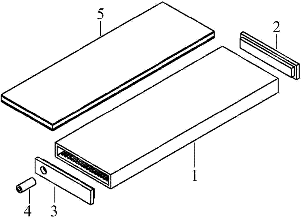
[0029] Such as Figure 1-Figure 4 As shown, the flat heat pipe according to one emb...


PUM


Abstract

The invention provides a flat heat pipe which comprises a plate body, a first end cap, a second end cap, a liquid inflation pipe and a capillary core. The upper inner surface and the lower inner surface of the plate body are each provided with a plurality of longitudinal grooves, the structures that a plurality of protruding ribs and the grooves are alternatively arranged are formed on the upper inner surface and the lower inner surface of the plate body, the first end cap and the second end cap are fixed to the two sides of the plate body, the liquid inflation pipe is fixedly connected to the second end cap, and the capillary core is arranged in the plate body; the upper surface and the lower surface of the capillary core are in contact with the surfaces of the protruding ribs, the upper surface and the lower surface of the protruding ribs and the grooves form a channel with a closed cross section, at an evaporation zone, the protruding ribs are in contact with the outer surface of the capillary core, a liquid working medium of a surface zone of the capillary core is heated to evaporate to enter the channel of the grooves, and the flowing resistance is reduced; at a condensation section, a gas working medium is in contact with the wall face of the plate body with the lower temperature, a cellular structure of the capillary core is rapidly transferred into liquid in the groove after gas condensates into liquid, the cold wall face has the efficient condensation capacity, the heat transferring heat resistance is reduced, and the condensation efficiency is improved.

Description

technical field [0001] The invention relates to the technical field of heat transfer, in particular to a flat heat pipe. Background technique [0002] With the rapid development of modern electronic technology, electronic equipment has been widely used in various fields of human life. Electronic devices are gradually developing towards high frequency, high speed, and high integration. The functions and complexity of integrated devices are increasing day by day, which leads to increasing heat dissipation power per unit volume of electronic equipment, higher and higher heat dissipation heat flux density, and electronic equipment failure. The rate is increasing, resulting in reduced reliability and service life of electronic equipment. [0003] The flat plate heat pipe is a high-efficiency phase change heat transfer device evolved from the traditional heat pipe. It has the advantages of flexible structure, good temperature uniformity, and high heat transfer efficiency. It is a...

Claims


Application Information

Patent Timeline
Patent Type & Authority Applications(China)
IPC IPC(8): F28D15/04
CPCF28D15/04F28D15/046
Inventor 赵雅楠梁惊涛
Owner TECHNICAL INST OF PHYSICS & CHEMISTRY - CHINESE ACAD OF SCI
Why Eureka
Try Eureka