Cavity-type light emitting diode lamp

A light-emitting diode lamp and cavity-type technology, which is applied to semiconductor devices, light sources, electric light sources, etc. The effect of weight reduction

Inactive Publication Date: 2011-11-09
INST OF ENGINEERING THERMOPHYSICS - CHINESE ACAD OF SCI
View PDF5 Cites 11 Cited by
  • Summary
  • Abstract
  • Description
  • Claims
  • Application Information

AI Technical Summary

Problems solved by technology

[0004] The purpose of the present invention is to disclose a cavity-type light-emitting diode (LED) lamp to solve the problems of insufficient heat dissipation of the LED chip of the existing LED lamp and the overweight and large volume of the LED lamp.

Method used


Image

  • Cavity-type light emitting diode lamp
  • Cavity-type light emitting diode lamp
  • Cavity-type light emitting diode lamp

Examples


Embodiment 1

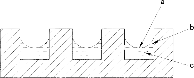
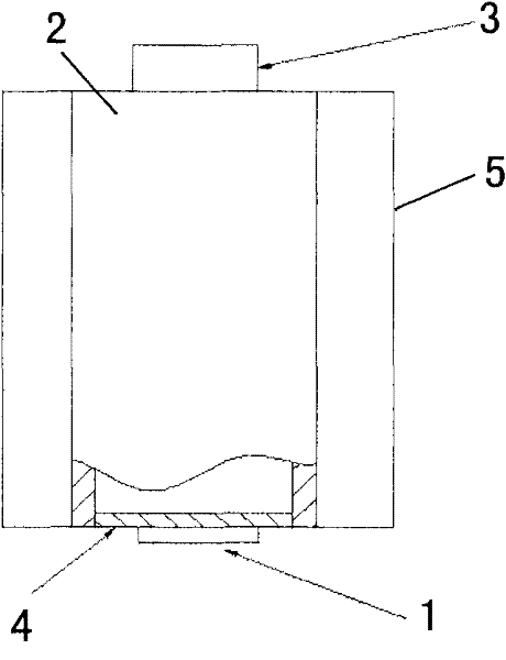
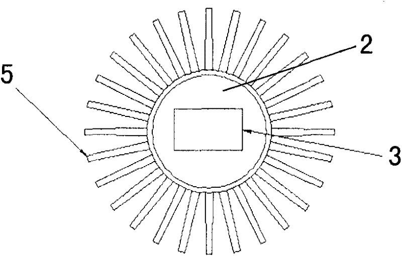
[0036] See Figure 2. The LED chip 1 is directly packaged on the front surface of a micro-groove group metal plate 4 with high thermal conductivity; the back side of the micro-groove group metal plate 4 is processed with a plurality of open rectangular fine channels to form an open rectangular micro-groove group. The width of the open rectangular micro-channels is in the range of 0.05-0.08mm, the depth of the micro-channels is in the range of 0.1-1mm, and the channel spacing is in the range of 1-2mm; the metal plate 4 of the micro-groove group faces outward The back side is packaged on the bottom wall of a cylindrical metal cavity 2 with a cavity inside. The cavity is filled with a liquid working medium with latent heat of vaporization; the outer surface of the cylindrical metal cavity 2 is provided with multiple ribs5. The height of the ribs 5 is in the range of 10-70 mm, the thickness is in the range of 1-5 mm, the length is in the range of 100-250 mm, and the distance betwe...

Embodiment 2

[0038] As shown in Fig. 3, the LED chip 1 is directly packaged on the front surface of a micro-groove group metal plate 4 with high thermal conductivity; the back side of the micro-groove group metal plate 4 is processed with a plurality of open rectangular fine channels to form an open rectangular microgroove group. The width of the open rectangular micro-channels is in the range of 0.04-0.07mm, the depth of the micro-channels is in the range of 0.15-1.2mm, and the channel spacing is in the range of 1-1.5mm; It is packaged outwardly and back inwardly on the cavity wall of a "return" type metal cavity 2 with a cavity inside, and the "return" type metal cavity 2 utilizes two thin-walled rectangular casings After the inner and outer coaxial sleeves are spaced apart, an annular passage is formed between the outer wall of the inner casing and the inner wall of the outer casing, and the upper and lower ends of the passage are sealed to form a closed cavity. Its cross section is li...


PUM

PropertyMeasurementUnit
heightaaaaaaaaaa
thicknessaaaaaaaaaa
thicknessaaaaaaaaaa

Abstract

The invention relates to a cavity-type light emitting diode lamp. A cooler is an enclosed metal cavity which is internally filled with a liquid working medium with latent heat of vaporization; a microgroove group metal plate is arranged on the cavity wall of the side or bottom of the metal cavity, and the periphery of the metal cavity is fixedly connected to the cavity wall of the metal cavity in a sealing mode; the back side of the metal cavity is provided with a microgroove group which is sealed in the cavity inward, and the frontage of the metal cavity is outward; the microgroove group is provided with a plurality of open-type microgroove channels, thus an open-type microgroove group is formed; an LED (light emitting diode) chip is encapsuled on the frontage of the metal plate, the light emitting surface of the chip is outward, the outer surface of the cavity wall at the top of the metal cavity is fixedly connected with a power supply, and the chip is electrically connected with a power supply; and the outer side wall of the cooler, except for the microgroove metal plate, is provided with fins. When the lamp works, the heat transfer process is intensified by high-strength minuteness scale composite phase-change of nucleate boiling of the liquid working medium, the liquid working medium is changes into steam, and the heat is taken away, expands on the surface of the metal cavity, and is released into the environment through the fins. The problems of insufficient heat radiation, over-heavy weight and overlarge volume of the existing LED lamp chip are solved.

Description

technical field [0001] The invention relates to the technical field of light-emitting diode (LED) lamps, and is a novel cavity-type light-emitting diode (LED) lamp, which is used for urban landscape, road traffic, home lighting, automobile, screen and other lighting and display. Background technique [0002] Light-emitting diode (LED) lamps have the advantages of low operating voltage, short response time, high efficiency and energy saving, stable operation, long life, and no pollution. [0003] LED lights are generally composed of three parts: LED chips, coolers and power supplies. Since about 80% of the energy of the LED chip is converted into heat energy during operation, the problem of heat dissipation of the LED chip becomes more and more serious as the power and integration of the LED chip increase. Excessively high LED chip temperature not only rapidly reduces the life of the LED, but also has a serious or even fatal impact on many performance parameters such as the ...

Claims


Application Information

Patent Timeline
Patent Type & Authority Applications(China)
IPC IPC(8): F21S8/00F21V17/00F21V19/00F21V23/00F21V29/00F21Y101/02F21V29/503F21V29/51F21Y115/10
Inventor 胡学功唐大伟王涛
Owner INST OF ENGINEERING THERMOPHYSICS - CHINESE ACAD OF SCI
Why Eureka
Try Eureka