Building bridge applying support frame with self-regulating function

A technology for bridges and support frames, applied in the field of building bridges, can solve the problems of troublesome construction, poor practicability, and increased construction costs, and achieve the effects of increased stability, strong practicability and reasonable structure

Inactive Publication Date: 2017-12-29
孙启成
View PDF1 Cites 9 Cited by
  • Summary
  • Abstract
  • Description
  • Claims
  • Application Information

AI Technical Summary

Problems solved by technology

[0003] Bridge is an inevitable construction project in railway construction and highway construction. Any terrain on the construction site will be encountered, especially where the terrain is difficult and the construction site is small, which brings great difficulties to erecting bridges, especially when erecting steel bridges. In the process of beam support construction, the traditional construction method is used to directly fix the whole. The construction is very troublesome and the process is cumbersome. It requires a lot of manpower and mechanical equipment, which leads to an increase in construction costs.
[0004] Chinese patent (notification number: CN204491414U) discloses a bridge support frame with self-adjusting function, including base and groove. During the process, the whole device is not very effective in stabilizing the bridge body, and it cannot play a very good role in self-regulation, and its practicability is poor.

Method used


Image

  • Building bridge applying support frame with self-regulating function
  • Building bridge applying support frame with self-regulating function
  • Building bridge applying support frame with self-regulating function

Examples


Embodiment Construction

[0023] It should be noted that, in the case of no conflict, the embodiments of the present invention and the features in the embodiments can be combined with each other.

[0024] In describing the present invention, it should be understood that the terms "center", "longitudinal", "transverse", "upper", "lower", "front", "rear", "left", "right", " The orientations or positional relationships indicated by "vertical", "horizontal", "top", "bottom", "inner" and "outer" are based on the orientations or positional relationships shown in the drawings, and are only for the convenience of describing the present invention and Simplified descriptions, rather than indicating or implying that the device or element referred to must have a particular orientation, be constructed and operate in a particular orientation, and thus should not be construed as limiting the invention. In addition, the terms "first", "second", etc. are used for descriptive purposes only, and should not be understood ...


PUM


Abstract

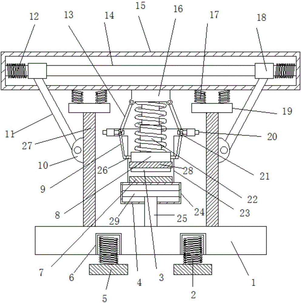
The invention discloses a support frame for building bridges with self-regulating function, which comprises a base, support beams are installed on both sides of the upper end of the base, a support plate is installed on the upper end of the support beam, a second spring is installed on the upper end of the support plate, and a second spring is installed on the upper end of the second spring. A beam is installed, a fixed block is installed in the middle of the outer side of the support beam, and a lifting rod is hinged in the middle of the fixed block. A lifting tube is installed between the lower end of the base and the beam. A clamping block is installed at the lower end of the spring, a first magnetic block is installed at the lower end of the clamping block, a second magnetic block is installed inside the lower end of the lifting cylinder, a piston cylinder is installed at the bottom of the lifting cylinder, and a fixed cylinder is installed on both sides of the upper end of the lifting cylinder to fix A slide bar is arranged inside the barrel. The present invention realizes the double stable support of the entire support frame structure for the bridge body, and the structure of the two stable support modes greatly increases the stability of the entire support frame, and can also be adjusted independently.

Description

technical field [0001] The invention relates to the technical field of building bridges, in particular to a support frame for building bridges with an autonomous adjustment function. Background technique [0002] Bridges generally refer to structures erected on rivers, lakes and seas to allow vehicles and pedestrians to pass smoothly. In order to adapt to the modern high-speed development of the transportation industry, bridges are also extended to buildings that cross mountain streams, poor geology or meet other transportation needs to make traffic more convenient. A bridge is generally composed of a superstructure, a substructure, a support and ancillary structures. The superstructure is also called a bridge span structure, which is the main structure for crossing obstacles; the substructure includes abutments, piers and foundations; Or the force transmission device installed at the supporting place of the bridge abutment; the auxiliary structures refer to the bridge head...

Claims


Application Information

Patent Timeline
Patent Type & Authority Applications(China)
IPC IPC(8): E01D21/00
CPCE01D21/00
Inventor 孙启成
Owner 孙启成
Why Eureka
Try Eureka