Electric control equipment facilitating circulation of hydraulic valve

A technology of electric control equipment and hydraulic valves, which is applied in the direction of mechanical equipment, valve operation/release devices, valve details, etc., can solve the problems of handle mishandling and false triggering of handles, and achieve the effect of avoiding mishandling and increasing the contact surface

Inactive Publication Date: 2017-12-29
LUZHOU JINGTONG FLUID HYDRAULIC MACHINERY
View PDF5 Cites 1 Cited by
  • Summary
  • Abstract
  • Description
  • Claims
  • Application Information

AI Technical Summary

Problems solved by technology

Since the handles are neatly arranged on one side of the multi-way valve body, when the handle is manually operated, it is easy to touch the handle next to it by mistake, so that the valve core connected to it moves, and the fluid f

Method used


Image

  • Electric control equipment facilitating circulation of hydraulic valve
  • Electric control equipment facilitating circulation of hydraulic valve
  • Electric control equipment facilitating circulation of hydraulic valve

Examples


Example Embodiment

[0035] Example 1

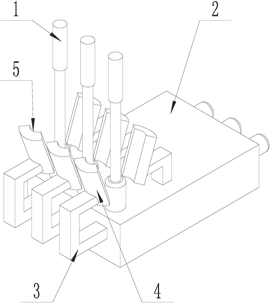
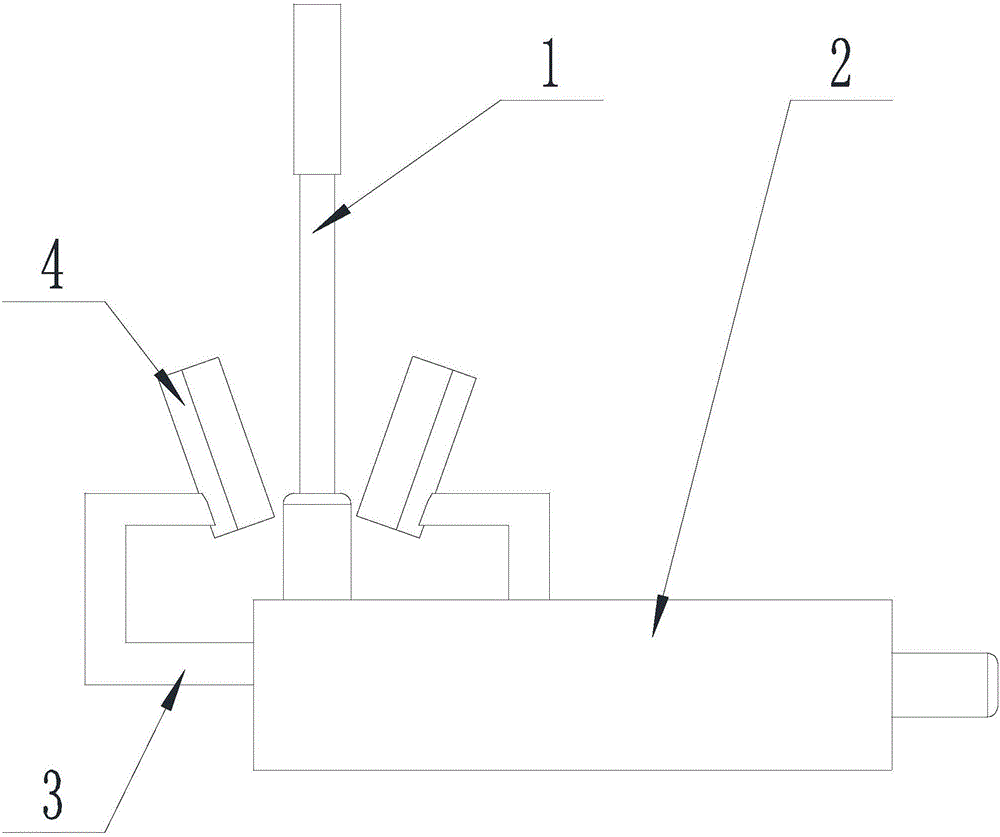
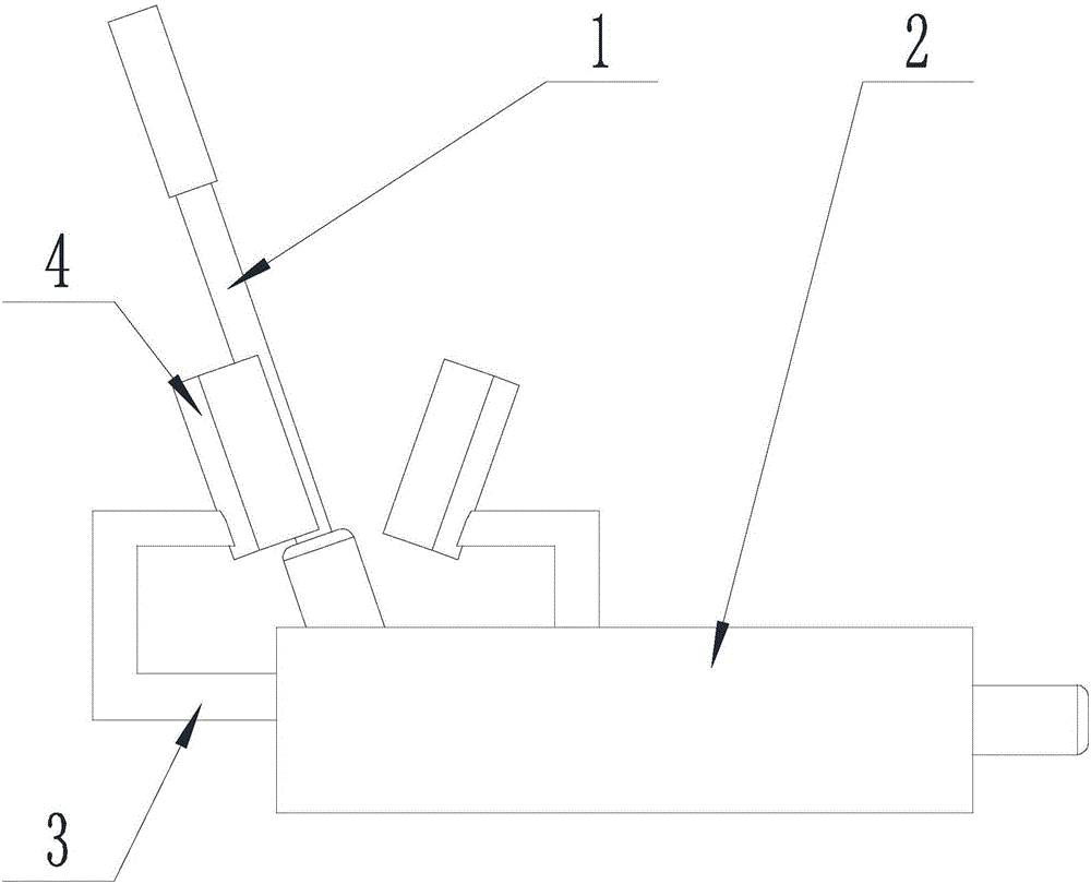
[0036] Such as Figure 1-Figure 4 As shown, the electronic control device for facilitating the circulation of hydraulic valves of the present invention includes a multi-way valve body 2 with a plurality of handles 1, and a limit component is arranged on the multi-way valve body 2, and the limit component includes sequentially connected The support 3 and the clamping block 4, the support 3 supports the clamping block 4 on one side of the handle 1, and the clamping block 4 is provided with a clamping slot 5 on the side close to the handle 1. An electromagnet is arranged in the positioning slot 5, and rotating the handle 1 can make the handle 1 be located in the positioning slot 5 and be attracted by the electromagnet.

[0037] The handle 1 in each station is fixed by the structure and components such as the locking slot 5 and the electromagnet to prevent it from being touched or operated by mistake, and then to avoid fluid flowing along the wrong path; at the same...

Example Embodiment

[0038] Example 2

[0039] The present invention is based on Embodiment 1, and further illustrates the present invention.

[0040] Such as Figure 1-Figure 4 As shown, the present invention is an electronic control device for facilitating the circulation of hydraulic valves. The axis of the retaining slot 5 passes through the rotation center of the handle 1, and the rotation of the handle 1 can make the axis of the handle 1 coincide with the axis of the retaining slot 5. The axis of the locking slot 5 passes through the center of rotation of the handle 1, and rotating the handle 1 can make the axis of the handle 1 coincide with the axis of the locking slot 5, which can increase the contact surface between the locking slot 5 and the handle 1, thereby enabling the electromagnet Fix the handle 1 more firmly.

[0041] Further, the cross section of the locking slot 5 is arc-shaped, and its radius is consistent with the radius of the handle 1. The cross section of the locking slot 5 is a...

Example Embodiment

[0042] Example 3

[0043] The present invention is based on Embodiment 1, and further illustrates the present invention.

[0044] Such as Figure 1-Figure 4 As shown, in the electronic control device of the present invention that facilitates the flow of hydraulic valves, the end surface of the locking block 4 away from the handle 1 is arc-shaped, and the end surface away from the handle 1 is convex. The arc-shaped end surface of the retaining block 4 away from the handle 1 is to match the shape of the retaining slot 5, so as to reduce the material required for the retaining block 4 and reduce the material cost.

[0045] Further, the number of the limit components is twice the number of the handles 1, and every two limit components are a pair, and the handles 1 are respectively located in a pair of limit components, and are located in the pair of limit components. The card is between block 4. In this way, no matter if the handle is in a position away from the valve core of the mult...


PUM


Abstract

The invention discloses an electric control device for facilitating the circulation of a hydraulic valve, which includes a multi-way valve body with several handles, and a limit assembly is arranged on the multi-way valve body, and the limit assembly includes a support piece and a card connected in sequence. A positioning block, the supporting member supports the positioning block on one side of the handle, a positioning slot is provided on the side of the positioning block close to the handle, an electromagnet is arranged in the positioning slot, and the rotating handle can make the The handle is located in the card slot and is attracted by the electromagnet. Through structures and components such as clamping slots and electromagnets, the handles at each station are fixed to prevent them from being accidentally touched and misoperated, thereby preventing the fluid from flowing along the wrong path; at the same time, when an object hits the handle When it is on, due to the adsorption effect of the electromagnet, the situation that the handle is accidentally touched and misoperated is avoided.

Description

technical field [0001] The invention relates to a multi-channel manual reversing valve, in particular to an electric control device for facilitating the circulation of hydraulic valves. Background technique [0002] The function of the hydraulic system is to increase the force by changing the pressure. A complete hydraulic system consists of five parts, namely power components, actuators, control components, auxiliary components (accessories) and hydraulic oil. Hydraulic systems can be divided into two categories: hydraulic transmission systems and hydraulic control systems. The main function of the hydraulic transmission system is to transmit power and motion. The hydraulic control system must make the output of the hydraulic system meet specific performance requirements (especially dynamic performance). The hydraulic system generally refers to the hydraulic transmission system. [0003] The function of the power element is to convert the mechanical energy of the prime m...

Claims


Application Information

Patent Timeline
IPC IPC(8): F16K35/16F16K31/60
CPCF16K35/16F16K31/60
Inventor 罗晓英李静
Owner LUZHOU JINGTONG FLUID HYDRAULIC MACHINERY
Why Eureka
Try Eureka