
Method and device for characterizing low-speed non-Darcy seepage characteristics of dense oil deposit

A tight oil reservoir, Darcy seepage technology, applied in the direction of measuring devices, surface/boundary effects, instruments, etc., can solve the problems of tight oil phase difference, high experiment cost, small seepage velocity, etc., to achieve short time-consuming and good results Accurate, low-experimental cost effects

Active Publication Date: 2017-12-29
CHINA UNIV OF PETROLEUM (BEIJING)
View PDF4 Cites 11 Cited by
  • Summary
  • Abstract
  • Description
  • Claims
  • Application Information

AI Technical Summary

Problems solved by technology

However, under low pressure gradient, the fluid seepage velocity is small, the flow measurement error is large, the measurement time is long, and the experimental cost is high.
[0008] In terms of model calculation methods, for example, patent application CN201410051469.8 proposes a method for predicting the start-up pressure gradient of Robertson-Steiff fluid in porous media, but the properties of tight oil are quite different from those of Robertson-Steiff fluid , and this method can only predict the pseudo-threshold pressure gradient, and cannot characterize the process of non-linear increase of fluid seepage velocity with the increase of pressure gradient

Method used


Image

  • Method and device for characterizing low-speed non-Darcy seepage characteristics of dense oil deposit
  • Method and device for characterizing low-speed non-Darcy seepage characteristics of dense oil deposit
  • Method and device for characterizing low-speed non-Darcy seepage characteristics of dense oil deposit

Examples


Embodiment

[0140] 1. Take a tight oil reservoir core, and measure the core porosity φ=0.143 by the saturated water weighing method;

[0141] 2. Carry out mercury injection test on the core, and obtain the mercury injection curve of the core, such as Figure 5 shown;

[0142] The pore diameter λ can be adjusted by the mercury injection pressure P c get:

[0143]

[0144] The displacement pressure of this core is P cd =0.639MPa, the maximum mercury injection pressure P cmax =83.44MPa, bring in The maximum pore diameter λ can be obtained max = 2.3 μm and minimum pore diameter λ min = 0.0292 μm.

[0145] The average pore diameter of this core is:

[0146]

[0147] S Hgi is the mercury saturation at a certain time point i, S Hgi-1 is the mercury saturation at the previous time point i-1, λ i-1 is the pore throat diameter at the previous time point i-1, λ i is the pore throat diameter at a certain time point i, where i represents a certain time point.

[0148] Calculate the...


PUM


Abstract

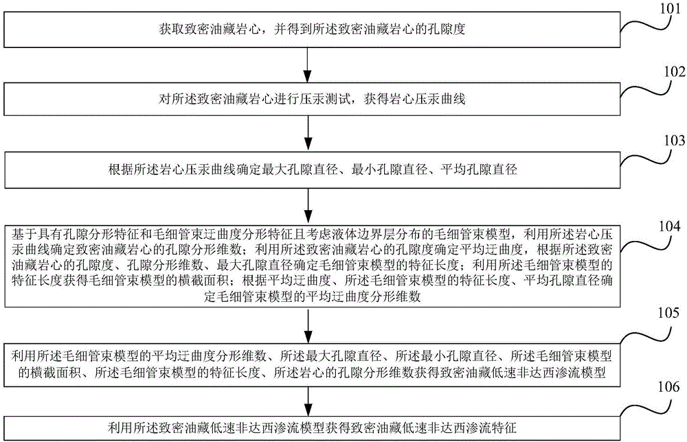
The invention relates to a method and a device for characterizing low-speed non-Darcy seepage characteristics of a dense oil deposit. The method comprises the following steps: obtaining a dense oil deposit rock core to obtain the porosity of the dense oil deposit rock core; determining a maximum pore diameter, a minimum pore diameter and an average pore diameter according to a rock core mercury injection curve; determining a pore fractal dimension by utilizing the rock core mercury injection curve; determining the average tortuosity by utilizing the porosity; determining the characteristic length of a capillary tube bundle model according to the porosity, the pore fractal dimension and the maximum pore diameter; obtaining a cross section area of the capillary tube bundle model by utilizing the characteristic length; determining an average tortuosity fractal dimension according to the average tortuosity, the characteristic length and the average pore diameter; obtaining a low-speed non-Darcy seepage model of the dense oil deposit by utilizing the average tortuosity fractal dimension, the maximum pore diameter, the minimum pore diameter, the cross section area, the characteristic length and the pore fractal dimension; obtaining the low-speed non-Darcy seepage characteristics of the dense oil deposit by utilizing the low-speed non-Darcy seepage model of the dense oil deposit.

Description

technical field [0001] The invention relates to the technical field of tight oil reservoirs, in particular to a method and device for accurately and quickly characterizing low-velocity non-Darcy seepage characteristics of tight oil reservoirs. Background technique [0002] my country is rich in tight oil reserves and has great potential for exploration and development. However, tight oil reservoirs are dense, with widely developed micro-nano pores, and have obvious low-velocity non-Darcy seepage characteristics under low pressure gradients. Accurately describing the law of low-velocity non-Darcy flow in tight oil is of great significance to the effective development of tight oil. [0003] Due to the small pore throats, complex pore structure, and large pore specific surface area of ​​tight oil reservoirs, the interaction between fluid and pore interface is significant and cannot be ignored. Liquid molecules are tightly adsorbed on the solid surface and arranged around it in ...

Claims


Application Information

Patent Timeline
IPC IPC(8): G01N13/04
CPCG01N13/04
Inventor 王付勇刘志超
Owner CHINA UNIV OF PETROLEUM (BEIJING)
Learn More