Motor rotor, permanent magnet motor and compressor

A technology of motor rotor and permanent magnet motor, which is applied in the field of compressors, can solve problems such as insufficient power density, and achieve the effect of increasing power density and reducing volume

Active Publication Date: 2017-12-29
GUANGDONG MEIZHI COMPRESSOR
View PDF7 Cites 11 Cited by
  • Summary
  • Abstract
  • Description
  • Claims
  • Application Information

AI Technical Summary

Problems solved by technology

[0002] A permanent magnet synchronous motor (IPM) is a motor that places a layer of permanent magnets inside the rotor and mainly uses permanent magnet torque and reluctance torque as auxiliary motors. In recent years, the

Method used


Image

  • Motor rotor, permanent magnet motor and compressor
  • Motor rotor, permanent magnet motor and compressor
  • Motor rotor, permanent magnet motor and compressor

Examples


Embodiment 1

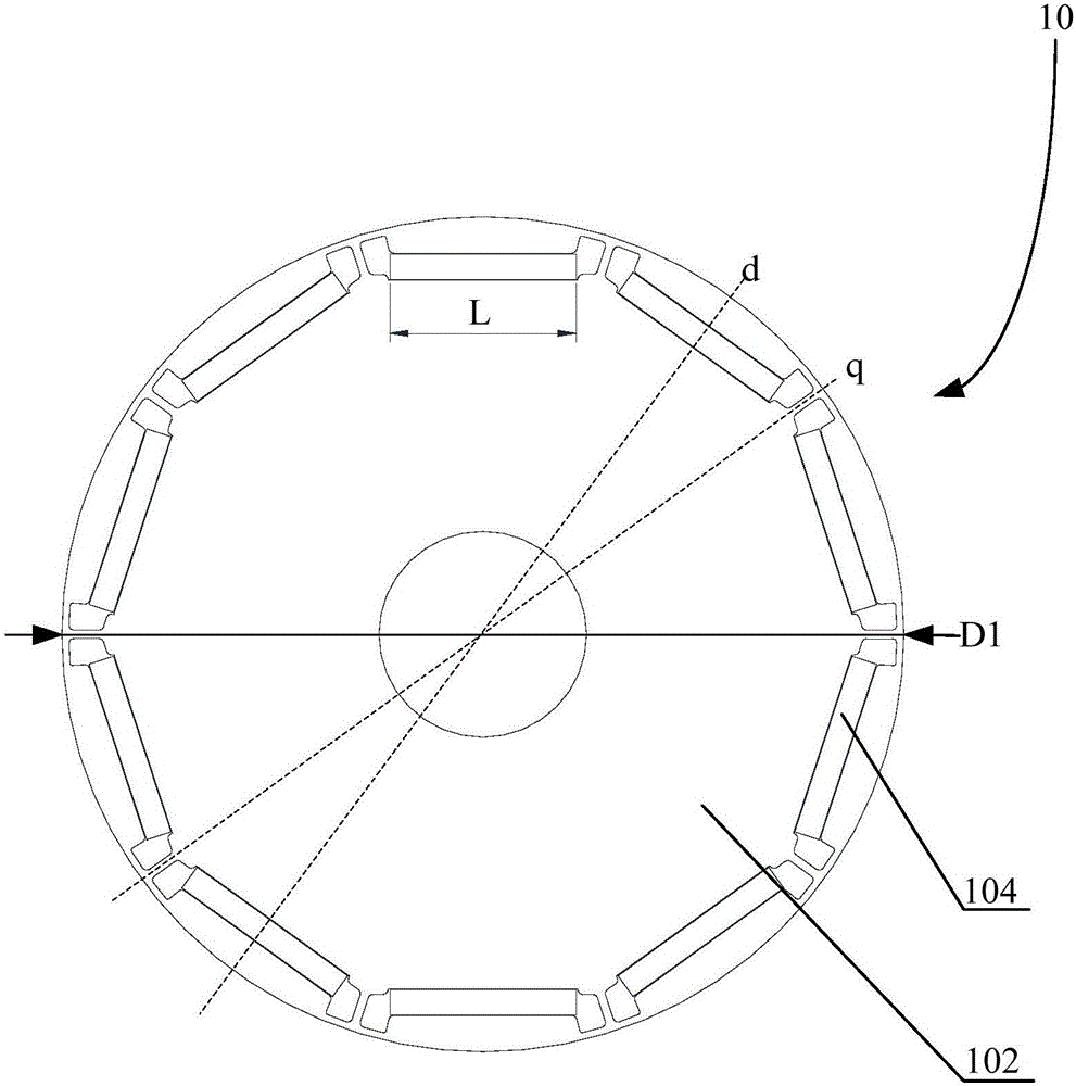
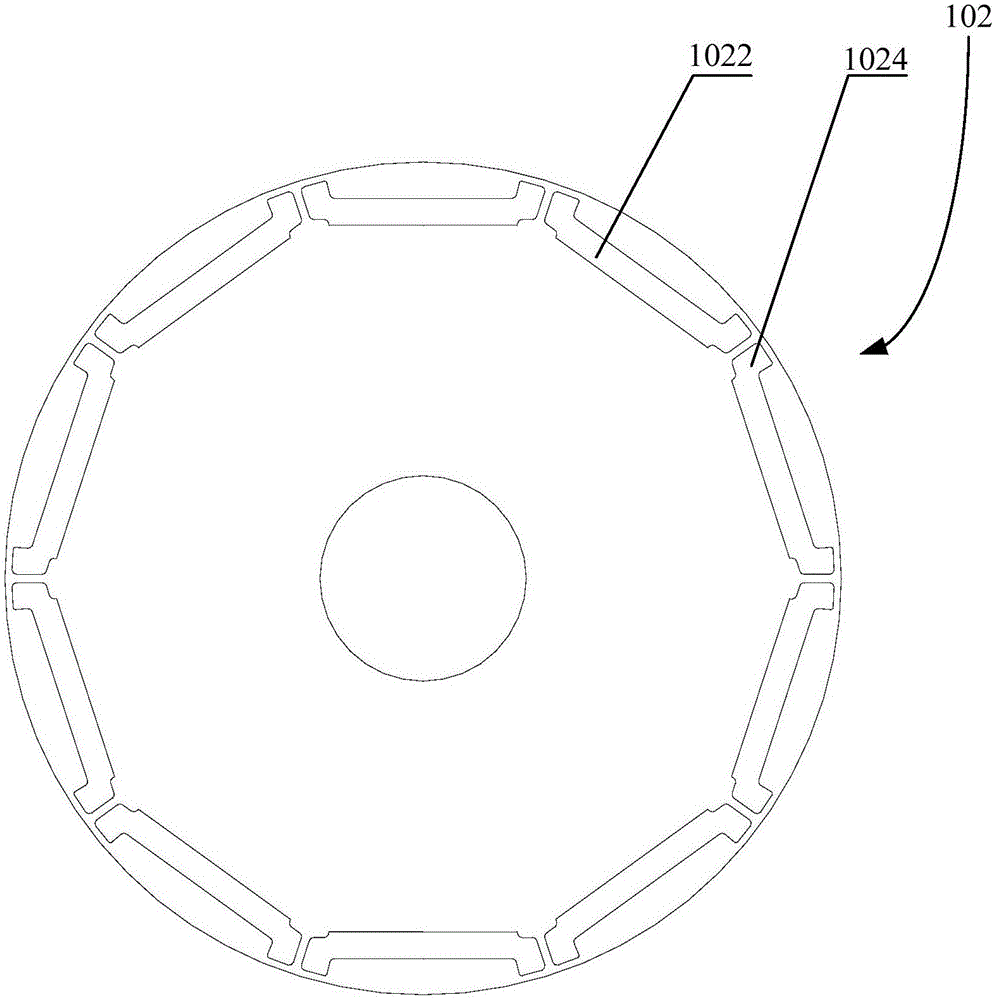
[0058] Such as Figure 1 to Figure 5 As shown, the motor rotor 10 according to the embodiment of the present invention is suitable for a compressor, including: a rotor core 102, a plurality of sets of receiving grooves 1022 are opened on the end surface of the rotor core 102 along the circumference of the rotor core 102; The permanent magnets 104 are correspondingly embedded in multiple sets of accommodation grooves 1022, and the permanent magnets 104 in each set of accommodation grooves 1022 form magnetic poles, wherein the number of magnetic poles is greater than or equal to 8 and less than or equal to 12, and the distance between the two ends of the magnetic poles is The distance is L, and the outer diameter of the rotor core 102 is D1, 0.18×D1≤L≤0.28×D1.

[0059] In this embodiment, the motor rotor 10 includes a rotor core 102 and a plurality of sets of accommodation grooves 1022 provided on the rotor iron core 102. The accommodation grooves 1022 are used to embed the perm...

Embodiment 2

[0072] Such as figure 1 As shown, specifically, the permanent magnets 104 under the same pole of the motor rotor 10 are arranged in a "one" shape structure, and the width of the permanent magnets 104 is L.

Embodiment 3

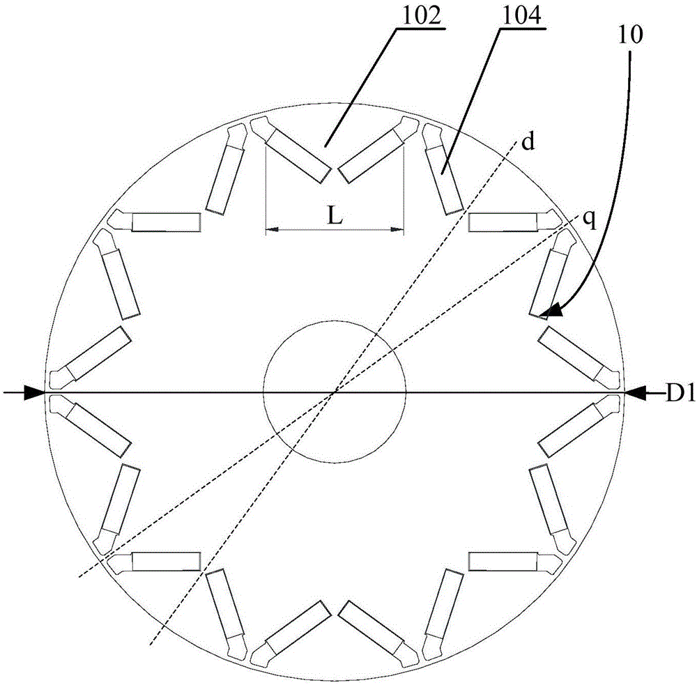
[0074] Such as image 3 As shown, the permanent magnets 104 under the same pole of the motor rotor 10 are arranged in a "V" shape, and the distance L between the two ends of the magnetic pole is smaller than the sum of the widths of all the permanent magnets 104 .


PUM

PropertyMeasurementUnit
Outer diameteraaaaaaaaaa

Abstract

The invention provides a motor rotor, a permanent magnet motor and a compressor. The motor rotor comprises a rotor iron core of which the end surface is provided with multiple sets of accommodating slots along the circumferential direction of the rotor iron core; and multiple permanent magnets which are correspondingly embedded in multiple sets of accommodating slots, and the permanent magnets in all sets of accommodating slots form magnetic poles, wherein the number of the magnetic poles is greater than or equal to eight and less than or equal to twelve, the distance between the two ends of the magnetic poles is L, the peripheral diameter of the rotor iron core is D1, and 0.18xD1<=L<=0.28xD1. With application of the technical scheme, the higher power density can be realized by limiting the dimension relationship between the peripheral diameter of the rotor iron core and the distance of the two ends of the magnetic poles with cooperation of increasing of the number of the magnetic poles; besides, the dimension of the motor rotor can be reduced by limiting the number of the magnetic poles so as to realize miniaturization of the motor.

Description

technical field [0001] The invention relates to the field of compressors, in particular to a motor rotor, a permanent magnet motor and a compressor. Background technique [0002] A permanent magnet synchronous motor (IPM) is a motor that places a layer of permanent magnets inside the rotor and mainly uses permanent magnet torque and reluctance torque as auxiliary motors. In recent years, the miniaturization of compressors has become a hot spot in industry research and application. The problem is that the miniaturization of permanent magnet motors using traditional technology may face problems such as insufficient power density. Therefore, there is a need for permanent magnet motor structures with higher power densities. [0003] In related technologies, the distance between the two ends of the permanent magnets under the same pole is more than 0.3 times the maximum diameter of the rotor. Although this structure can meet the performance requirements of conventional compresso...

Claims


Application Information

Patent Timeline
IPC IPC(8): H02K1/27H02K21/14
CPCH02K1/2766H02K21/14H02K2213/03
Inventor 乔正忠虞阳波邱小华
Owner GUANGDONG MEIZHI COMPRESSOR
Why Eureka
Try Eureka