Method and device for molding sterile container, and method and device for sterile filling

A technology of aseptic container and molding method, which is applied to household components, household appliances, other household appliances, etc., can solve the problems of increasing consumption of hydrogen peroxide, increasing mist flow, etc., and achieve the effect of improving sterilization effect and preventing corrosion.

Active Publication Date: 2018-01-02
DAI NIPPON PRINTING CO LTD
View PDF4 Cites 1 Cited by
  • Summary
  • Abstract
  • Description
  • Claims
  • Application Information

AI Technical Summary

Problems solved by technology

However, there is a problem that this leads to an increase in the consumption of hydrogen peroxide
In addition, if the travel speed of the bottle is increased in order to improve the production efficiency of the aseptic package, the flow rate of the mist must be further increased, which will lead to a further increase in the consumption of hydrogen peroxide.

Method used


Image

  • Method and device for molding sterile container, and method and device for sterile filling
  • Method and device for molding sterile container, and method and device for sterile filling
  • Method and device for molding sterile container, and method and device for sterile filling

Examples


Embodiment approach 1

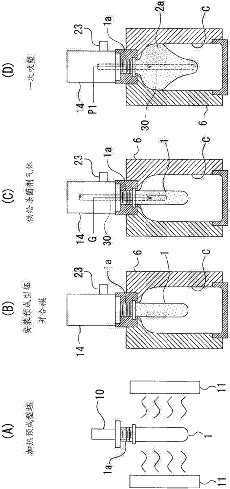
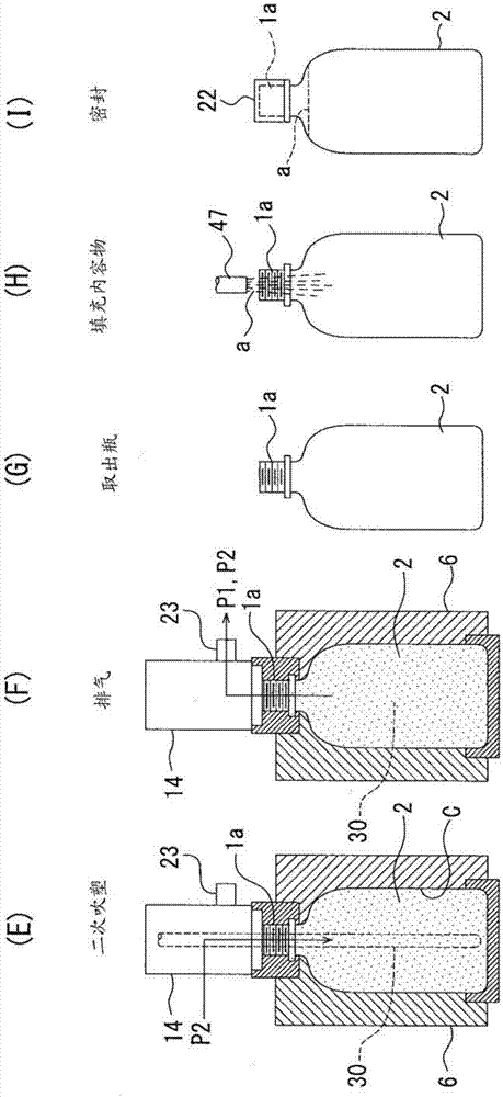
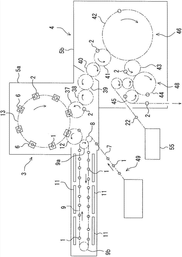
[0045] Such as image 3 As shown, the aseptic filling device is equipped with the ability to sequentially supply preforms 1 at predetermined intervals (refer to figure 1 (A)) the preform supply machine 49, the preform 1 is molded into a bottle 2 as a container (refer to figure 2 (G)) the blow molding machine 3, for the bottle 2 after molding, content a such as beverage (referring to figure 2 (H)(I)) The filling machine 4 that fills the bottle 2 and seals it.

[0046] The position from the preform supply machine 49 to the filling machine 4 is covered with chambers 5a, 5b as protective covers. The interior of chambers 5a and 5b is maintained at a positive pressure by always supplying sterile air from a sterile air supply source not shown in the figure.

[0047] Preform 1 as figure 1 As shown in (A), it is a test tube-shaped bottomed cylindrical body, which is made of PET (polyethylene terephthalate), for example, by injection molding or the like. The preform 1 is finished...

Embodiment approach 2

[0132] Such as Figure 7 As shown, in this second embodiment, an air flushing nozzle 54 for air flushing the bottle 2 is provided on the conveyance path of the molded bottle 2 between the blow molding machine 3 and the filling machine 4 .

[0133] One or more nozzles 54 for air washing are arranged around the wheel 39, for example. Instead of the wheel 39 or in addition to or in addition to the wheel 39, it may be arranged around the wheel 37, the wheel 40, or the wheel 41.

[0134] In addition, a delivery duct (not shown) positively pressurized with sterile air may be provided around the wheel 39 and the like, and the bottle 2 may be passed through the delivery duct to blow sterile air into the bottle 2 . Air. Thereby, air flushing of the bottle 2 can also be performed.

[0135] When the bottle 2 molded by the molding die 6 of the blow molding machine 3 is traveling around the wheel 39, as Figure 8 As shown in (A), sterile air N is blown from the nozzle 54 for air washin...


PUM


Abstract

The present invention sterilizes a container during the blow molding. A heated preform (1) is introduced into a mold (6), which is then closed. A mist or gas of a sterilizer or a mixture of these is blown into the preform (1). Air for blow molding is then blown into the preform (1) to expand the preform (1) to the dimensions of a finished container (2). The used air for blow molding is dischargedfrom inside the container (2) to remove the sterilizer from the inside of the container (2).

Description

technical field [0001] The present invention relates to a method and device for molding aseptic containers such as bottles, and an aseptic filling method and device using the same. Background technique [0002] There is proposed an arrangement system for manufacturing PET (polyethylene terephthalate) bottles by arranging blow molding machines on a production line for contents such as beverages, and then aseptically filling the contents in the bottles (for example, refer to Patent Documents 1, 2.). [0003] In addition, in the same array system, there are those in which the sterilization of the bottle and the molding of the bottle are performed simultaneously by blowing blowing gas of 110° C. or higher into the preform, and the aseptic bottle is intended to be supplied to Contents filling line (for example, refer to Patent Document 1.) There is also the following one: conveying preforms while blow molding PET bottles, while continuing to drive the bottles, from nozzles insta...

Claims


Application Information

Patent Timeline
Patent Type & Authority Applications(China)
IPC IPC(8): B29C49/46B29C49/06B29C49/18
CPCB29C49/06B29C49/18B29C49/12B29C49/4289B29C2049/4697B29C2049/4889B29C49/46B29C2049/4635B29K2067/003B29L2031/7158B29C49/58B29C49/42405B29C49/42418B29C49/42802B29C49/42808B29C49/42822B29C2949/0715B29C2049/7832B29C2049/4664
Inventor 早川睦
Owner DAI NIPPON PRINTING CO LTD
Why Eureka
Try Eureka