Wear-resistant liner with asymmetrical lifting strip for semi-autogenous mill

A technology of semi-autogenous mills and wear-resistant linings, applied in grain processing, etc., can solve the problems of increasing the production cost of symmetrical cylinder linings, reducing the amount of material filling in the mill, and reducing the working efficiency of the mill, etc., to achieve Simple structure, improved grinding efficiency, convenient and efficient use

Pending Publication Date: 2018-01-05
中实洛阳重型机械有限公司
View PDF4 Cites 5 Cited by
  • Summary
  • Abstract
  • Description
  • Claims
  • Application Information

AI Technical Summary

Problems solved by technology

[0003] In the prior art, the main problems of cylinder liners with symmetrical lifting strips are: 1. When the symmetrical lifting strip cylinder liners are used until they are scrapped, the back spherical surface of the lifting strips wears less, resulting in the loss of raw materials during casting. Waste, which virtually increases the production cost of manufacturing symmetrical cylinder liners; 2. Causes unnecessary loads in the working state of the mill and occupies the inner space of the mill, thereby reducing the amount of material filling in the mill and reducing the load of the mill. Work efficiency; based on the defects in the prior art, the inventor has developed a wear-resistant liner for semi-autogenous mills with asymmetric lifting strips, which can solve the problems in the prior art

Method used


Image

  • Wear-resistant liner with asymmetrical lifting strip for semi-autogenous mill

Examples


Embodiment 1

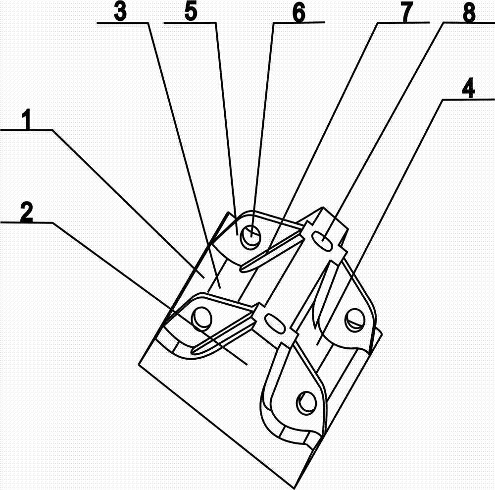
[0032] The surface connecting the lifting strip 2 with the left liner body 1 is the spherical surface 3, and the angle between the spherical surface 3 and the liner body 1 is 45°; the surface connected with the lifting strip 2 and the right liner body 1 is the back spherical surface 4. The included angle between the back spherical surface 4 and the liner body 1 is 60°, and the joints between the front spherical surface 3 and the back spherical surface 4 and the liner body are rounded transitions.

Embodiment 2

[0034] The surface connecting the lifting strip 2 with the left liner body 1 is the spherical surface 3, and the angle between the spherical surface 3 and the liner body 1 is 50°; the surface connected with the lifting strip 2 and the right liner body 1 is the back spherical surface 4. The included angle between the back spherical surface 4 and the liner body 1 is 70°, and the joints between the front spherical surface 3 and the back spherical surface 4 and the liner body are rounded transitions.

Embodiment 3

[0036] The surface connecting the lifting strip 2 with the left liner body 1 is the spherical surface 3, and the angle between the spherical surface 3 and the liner body 1 is 60°; the surface connected with the lifting strip 2 and the right liner body 1 is the back spherical surface 4. The included angle between the back spherical surface 4 and the liner body 1 is 80°, and the connection between the front spherical surface 3 and the back spherical surface 4 and the liner body is a round transition.


PUM


Abstract

The invention discloses a wear-resistant liner with an asymmetrical lifting strip for a semi-autogenous mill. The wear-resistant liner comprises a liner body, the lifting strip, a ball approaching surface and a ball deviating surface, wherein the liner body is arranged at the bottom, and the lifting strip is fixedly arranged in the middle of the liner body; mounting holes are fixedly formed in thefront and the back of the upper part of the lifting strip, and reinforcing strips are fixedly arranged at the front and back sides of the mounting holes of the lifting strip; the upper parts of the reinforcing strips are connected with the upper part of the lifting strip, and the lower parts of the reinforcing strips are fixedly connected with the liner body; the mounting holes are uniformly formed in the upper part of the lifting strip at equal distance. The wear-resistant liner with the asymmetrical lifting strip for the semi-autogenous mill has the advantages of greatly improving the milling efficiency of the semi-autogenous mill, reducing the waste of raw materials when a liner is cast, increasing the filling amount of the materials in the mill, increasing the production of the semi-autogenous mill, and prolonging the service life of the wear-resistant liner.

Description

technical field [0001] The invention belongs to the technical field of wear-resistant liners for semi-autogenous mills, and in particular relates to a wear-resistant liner for semi-autogenous mills with asymmetric lifting strips. Background technique [0002] The semi-autogenous mill adds a small amount of steel balls into the mill on the basis of the autogenous mill, taking into account the advantages of the autogenous mill using the material itself as the medium to achieve crushing through mutual impact and grinding, and at the same time under the same conditions It can also improve the material handling capacity and reduce the energy consumption per unit of product, but the wear of the liner will increase relatively, and the product fineness will also become coarser. The cylinder liner installed in the semi-autogenous mill is impacted and rubbed with materials and steel balls during the working process, and the wear is serious. In different directions of rotation, the we...

Claims


Application Information

Patent Timeline
Patent Type & Authority Applications(China)
IPC IPC(8): B02C17/22B02C17/10
Inventor 姜伟田亮孙雪磊马金萍刘洋钱峰
Owner 中实洛阳重型机械有限公司
Why Eureka
Try Eureka