Square full-automatic welding machine

A fully automatic welding, square technology, applied in welding equipment, non-electric welding equipment, metal processing equipment, etc., can solve the problems of long welding time, high resistivity, high labor cost, etc., and achieve neat welding nodes and high dimensional uniformity. , the effect of high degree of automation

Pending Publication Date: 2018-01-05
ANWHA SHANGHAI AUTOMATION ENG
View PDF7 Cites 2 Cited by
  • Summary
  • Abstract
  • Description
  • Claims
  • Application Information

AI Technical Summary

Problems solved by technology

[0002] The traditional welding method of the workpiece is manual welding, which has low efficiency and high labor cost, and the welding quality cannot be guaranteed, and the welding size cannot be unified
[0003] Moreover, the soldering leg welded by the prior art is an arc-shaped soldering leg, the electrical conductivity is poor after welding, and the resistivity is extremely high
In addition, manual welding is based on the welding of molten materials, which will weaken the metal properties; and has high requirements on the surface of the welded metal; the welding time is long, and requires the help of flux, gas, and solder; welding produces a lot of sparks, pollutes the environment, and is harmful to welding. Physically vulnerable to injury

Method used


Image

  • Square full-automatic welding machine
  • Square full-automatic welding machine
  • Square full-automatic welding machine

Examples


Embodiment Construction

[0023] In order to make the object, technical solution and advantages of the present invention clearer, the present invention will be further described in detail below in combination with specific examples and with reference to the accompanying drawings. It should be understood that these descriptions are exemplary only, and are not intended to limit the scope of the present invention. Also, in the following description, descriptions of well-known structures and techniques are omitted to avoid unnecessarily obscuring the concept of the present invention.

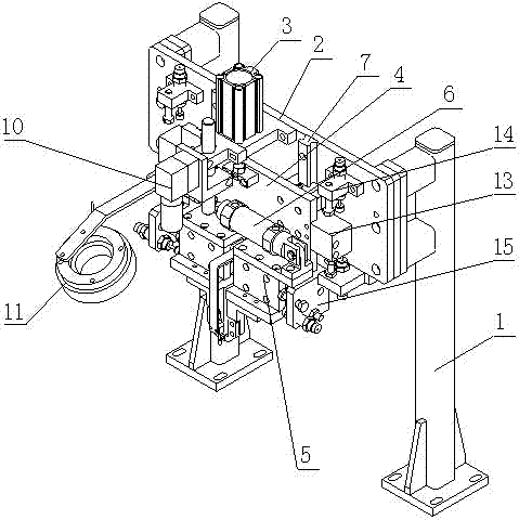
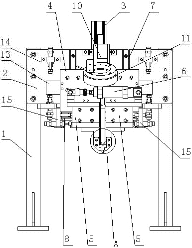
[0024] Such as Figure 1 to Figure 4 Shown:

[0025] A square fully automatic welding machine, comprising a clamping mechanism and an ultrasonic welding machine, the clamping mechanism comprising a bracket 1, a bracket connecting plate 2 arranged on one side of the bracket 1, a vertical cylinder 3 arranged on the top of the bracket connecting plate 2 , the vertical slide plate 4 that is located at the bottom of the vertica...


PUM


Abstract

The invention discloses a square full-automatic welding machine. The square full-automatic welding machine comprises a clamping mechanism and an ultrasonic welding machine, wherein the clamping mechanism comprises a bracket, a bracket connecting plate arranged on one side of the bracket, a vertical cylinder arranged on the bracket connecting plate, a vertical sliding plate arranged below the vertical cylinder, horizontal sliding plates arranged below the vertical sliding plate, and a horizontal cylinder arranged on the horizontal sliding plates; an output shaft end of the vertical cylinder isconnected with the vertical sliding plate; vertical guide rails are arranged between the vertical sliding plate and the bracket connecting plate; horizontal guide rails are arranged between the horizontal sliding plates and the vertical sliding plate; the two horizontal sliding plates can horizontally slide on the horizontal guide rails; conducting wire clamps are arranged under the two horizontalsliding plates; the conducting wire clamps are oppositely arranged and are used for clamping to-be-welded conducting wires; and a detection camera used for detecting the welding position and weldingquality of welding parts and a light source are further arranged on the bracket connecting plate. The square full-automatic welding machine has the beneficial effects that welding efficiency is high,welding joints are neat, and size uniformity is high.

Description

technical field [0001] The invention relates to the technical field of welding machines, in particular to a square fully automatic welding machine with high welding efficiency, neat welding nodes and high size uniformity. Background technique [0002] The traditional welding method of the workpiece is manual welding, which has low efficiency and high labor cost, and the welding quality cannot be guaranteed, and the welding size cannot be unified. [0003] In addition, the welding leg welded in the prior art is an arc-shaped welding leg, which has poor electrical conductivity after welding and extremely high resistivity. In addition, manual welding is based on the welding of molten materials, which will weaken the metal properties; and has high requirements on the surface of the welded metal; the welding time is long, and requires the help of flux, gas, and solder; welding produces a lot of sparks, pollutes the environment, and is harmful to welding. Personnel are vulnerable...

Claims


Application Information

Patent Timeline
Patent Type & Authority Applications(China)
IPC IPC(8): B23K20/10
Inventor 王鹏飞佀畅刘建坤李星宇邝应清
Owner ANWHA SHANGHAI AUTOMATION ENG
Why Eureka
Try Eureka