Motor synchronous wheel assembling equipment

A motor synchronous wheel and assembly equipment technology, applied in metal processing equipment, metal processing, manufacturing tools, etc., can solve the problems of high labor intensity, low efficiency, unstable quality of motor products, etc., achieve simple structure and improve production efficiency , Improve the effect of assembly quality

Active Publication Date: 2018-01-05
SHANGHAI MINGHUA ELECTRIC POWER TECH & ENG
View PDF7 Cites 9 Cited by
  • Summary
  • Abstract
  • Description
  • Claims
  • Application Information

AI Technical Summary

Problems solved by technology

[0003] At present, when assembling the synchronous wheel of the motor, the commonly used operation method is: first assemble the stator and the rotor separately and then install the synchronous wheel, and then use a press machine to install the synchronous wheel to the protruding part of the motor stator shaft. , it is necessary to manually pick up the synchronous wheel and put it on the motor stator shaft in the vehicle. After pressing the switch to turn on the machine, press and fit the synchronous wheel, and then remove it. When placing the synchronous wheel manually, it will take a long time The fatigue caused by the operation will make the synchronous wheel placed tilted, which will cause the quality of the finished motor to be unstable, which will make the labor intensity of the workers high and the efficiency low

Method used


Image

  • Motor synchronous wheel assembling equipment
  • Motor synchronous wheel assembling equipment
  • Motor synchronous wheel assembling equipment

Examples


Embodiment Construction

[0032] In order to enable those skilled in the art to better understand the technical solution of the present invention, the present invention will be described in detail below in conjunction with the accompanying drawings. The description in this part is only exemplary and explanatory, and should not have any limiting effect on the protection scope of the present invention. .

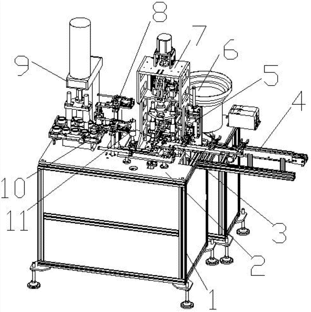
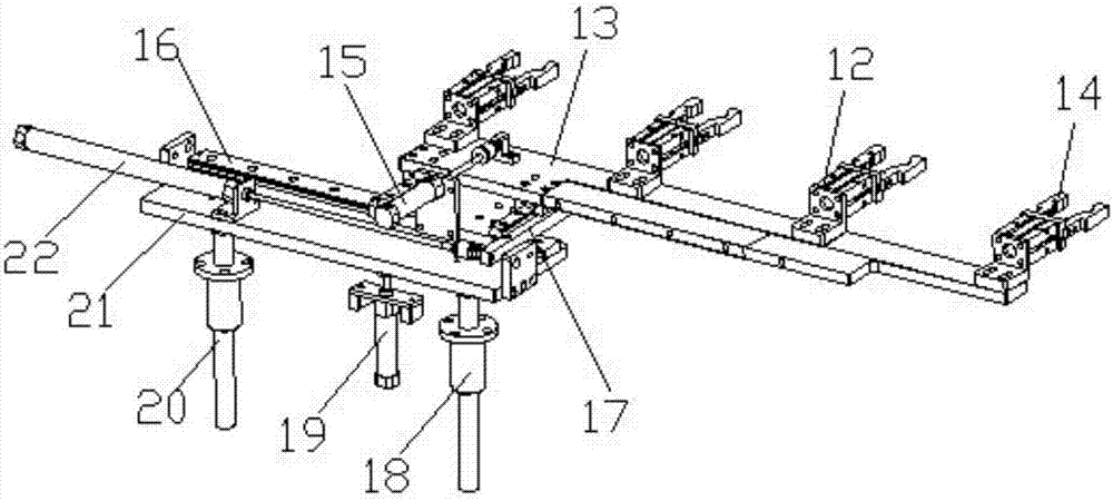
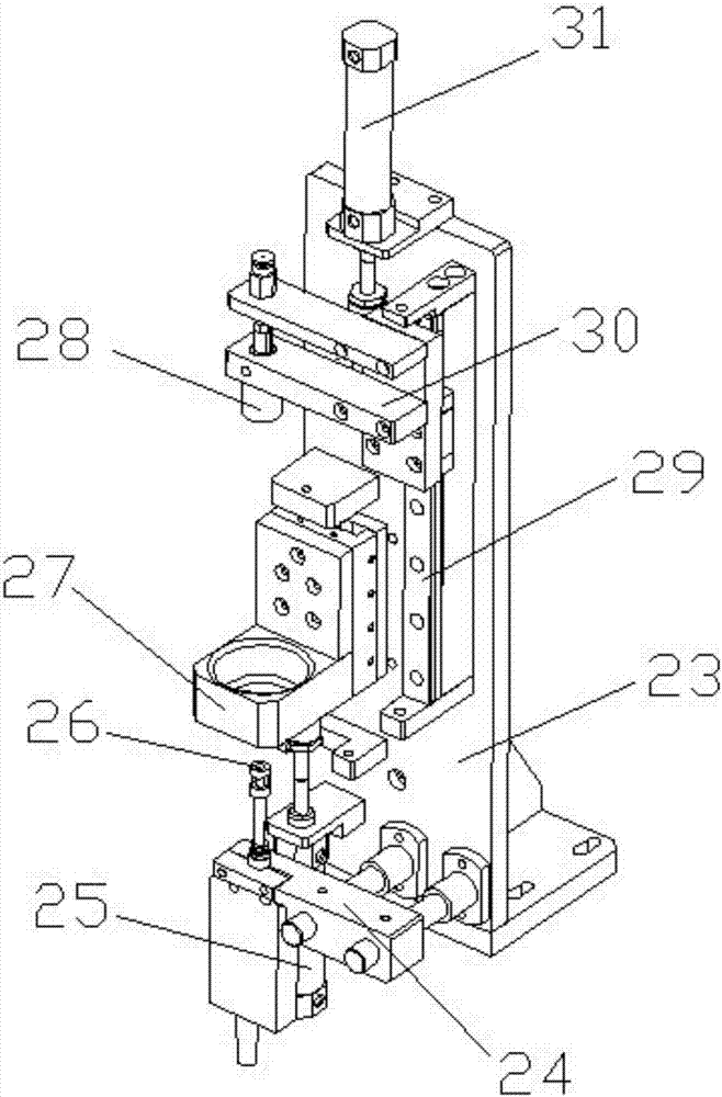
[0033] like Figure 1-Figure 9 As shown, the structure of the present invention is: a motor synchronous wheel assembly equipment, which includes a control box 1, a frame 2 arranged on the top of the control box 1, the right side of the frame 2 is provided with a motor delivery device 4, the The frame 2 is provided with a pressing wheel mechanism 7 that cooperates with the left side of the motor delivery device 4, and the rear side of the pressing wheel mechanism 7 is provided with a synchronous wheel feeding device 6 that cooperates with it on the frame 2. The wheel mechanism 7 includes a pressure rol...


PUM


Abstract

The invention relates to the field of motor assembling, in particular to motor synchronous wheel assembling equipment. The motor synchronous wheel assembling equipment comprises a control cabinet anda machine frame arranged on the control cabinet. A motor conveying device and a pressing wheel mechanism which are matched with each other are arranged on the machine frame. A synchronous wheel feeding device matched with the pressing wheel mechanism is arranged on the part, on the machine frame, of the rear side of the pressing wheel mechanism. The motor conveying device, the pressing wheel mechanism and the synchronous wheel feeding device are connected with the control cabinet. A motor is limited through a positioning device of the pressing wheel mechanism, meanwhile, a synchronous wheel ispositioned by the positioning device, the positioning device is pressed by a slow pressing head to drive a motor product on the positioning device to push downwards, the synchronous wheel on the positioning device is arranged on a shaft of the motor in a sleeving mode, and the problem that cracks of the synchronous wheel are caused during press-assembling due to the fact that the synchronous wheel is placed obliquely is solved, so that the motor assembling quality is greatly improved.

Description

technical field [0001] The invention belongs to the field of motor assembly, in particular to a motor synchronous wheel assembly equipment. Background technique [0002] The motor synchronous wheel is a transmission mechanism installed on the motor shaft. It is generally made of 45# steel, aluminum alloy, copper, nylon and other materials. It has accurate transmission, stable transmission, high transmission efficiency and convenient maintenance. And other advantages, so it is widely used in new mechanical belt drives in various industries such as machine tools, textiles, printing, food packaging, wires and cables, instruments, petrochemicals, tobacco, and communications. [0003] At present, when assembling the synchronous wheel of the motor, the commonly used operation method is: first assemble the stator and the rotor separately and then install the synchronous wheel, and then use a press machine to install the synchronous wheel to the protruding part of the motor stator s...

Claims


Application Information

Patent Timeline
Patent Type & Authority Applications(China)
IPC IPC(8): B23P19/027
CPCB23P19/027
Inventor 邓君杨坤
Owner SHANGHAI MINGHUA ELECTRIC POWER TECH & ENG
Why Eureka
Try Eureka