Filling device special for injectable suspension

A filling device and suspension technology, which is applied in the field of special filling devices for suspensions containing fine solids, can solve the problems of the filling device being difficult to clean, the wear of the piston and its sealing parts, the liquid affecting the filling, and the like. Achieve the effect of solving poor fluidity, improving filling quality, and preventing concentration changes

Active Publication Date: 2018-01-05
苏州康乐辉医药科技有限公司
View PDF7 Cites 2 Cited by
  • Summary
  • Abstract
  • Description
  • Claims
  • Application Information

AI Technical Summary

Problems solved by technology

[0002] Filling is an essential link in the production process of beverages, liquid medicines and other liquids. Currently, the commonly used filling method is mainly piston filling, but the piston filling has the following disadvantages: 1. The reciprocating movement of the piston will cause the piston and There are different degrees of wear on the sealing part, which will affect the filled liquid and affect the product quality; 2. The residue of the liquid medicine in the sealing part of the piston usually makes the filling device difficult to clean and cross-contamination; 3. For suspension Liquid filling, the liquid medicine cannot be continuously circulated during filling, and the suspension without circulation will have unstable components, such as concentration changes, sedimentation, etc., which will affect the filling quality
Currently commonly used filling equipment, the suspension cannot be in a circulating state all the time, resulting in changes in the concentration of the suspension during the filling process. Inconsistencies in the concentration of the suspension will affect product quality
[0004] To sum up, it can be seen that a new type of suspension filling device is currently needed to solve the problem that the suspension cannot be in a circulating state when filling, so that the concentration is uniform and the product quality is stable

Method used


Image

  • Filling device special for injectable suspension

Examples


Embodiment Construction

[0026] In order to make the purpose, technical solutions and advantages of the present invention more clear, the present invention will be further described in detail below in conjunction with specific examples. It should be understood that these descriptions are exemplary only, and are not intended to limit the scope of the present invention. Also, in the following description, descriptions of well-known structures and techniques are omitted to avoid unnecessarily obscuring the concept of the present invention.

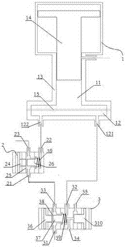
[0027] A special filling device for suspension, such as figure 1 As shown, it includes a dosing device 1, a dosing control valve 2 and a filling head 3.

[0028] Described quantitative device 1 comprises piston type pressurization device 11 and is located at the quantitative chamber 12 of described piston type pressurized device 11 bottom, and described quantitative chamber 12 bottom is provided with quantitative chamber inlet 121 and quantitative chamber outlet 122...


PUM


Abstract

The invention discloses a filling device special for an injectable suspension. The filling device comprises a dosing device, a dosing control valve and a filling head. The dosing device comprises a piston booster device and a dosing cavity. A dosing cavity inlet and a dosing cavity outlet are formed in the lower part of the dosing cavity. The dosing cavity is connected with the filling head. The dosing control valve is a three-way valve and comprises two inlets and a liquid outlet. One of the inlets is connected with the filling head. The other inlet is connected with the dosing cavity outlet.The filling head is internally provided with a control valve set. A liquid inlet, a dosing cavity connecting opening, a dosing control valve connecting opening, a filling opening and a liquid discharging opening are formed in the filling head. The dosing cavity connecting opening in the filling head is connected with the dosing cavity inlet. The dosing control valve connecting opening is connected with one inlet of the dosing control valve. The liquid discharging opening is controlled to communicate with the filling opening through a piston. A filling container is arranged at the lower part of the filling opening. Liquid can be made to be always at a circulation state in the filling process, the consistency of concentration of the injectable suspension is ensured, the filling quality is ensured, and a non-mixed suspension liquid can be filled.

Description

technical field [0001] The invention relates to the technical field of liquid filling, in particular to a special filling device for suspension containing fine solids. Background technique [0002] Filling is an essential link in the production process of beverages, liquid medicines and other liquids. Currently, the commonly used filling method is mainly piston filling, but the piston filling has the following disadvantages: 1. The reciprocating movement of the piston will cause the piston and There are different degrees of wear on the sealing part, which will affect the filled liquid and affect the product quality; 2. The residue of the liquid medicine in the sealing part of the piston usually makes the filling device difficult to clean and cross-contamination; 3. For suspension Liquid filling, the liquid medicine cannot be continuously circulated during filling, and the suspension without circulation will have unstable components, such as concentration changes and sediment...

Claims


Application Information

Patent Timeline
Patent Type & Authority Applications(China)
IPC IPC(8): B65B3/00B65B3/12B65B3/32
CPCB65B3/00B65B3/12B65B3/32
Inventor 张善勇
Owner 苏州康乐辉医药科技有限公司
Why Eureka
Try Eureka