Secondary ink box for ink-jet printer

An inkjet printer, secondary ink cartridge technology, applied in printing and other directions, can solve the problems of unstable ink circulation pressure, easy to be polluted or generated bubbles, easy to receive pollution, etc., to reduce the possibility of pollution and bubble generation, Guarantee printing stability and avoid the effect of ink precipitation

Active Publication Date: 2022-03-22
BEIJING ZHONGDIAN YUANDE TECH CO LTD
View PDF13 Cites 1 Cited by
  • Summary
  • Abstract
  • Description
  • Claims
  • Application Information

AI Technical Summary

Problems solved by technology

In the prior art disclosed by Chinese patent CN206394248U, the main ink tank, the air-removing device, the first sub-ink box, the nozzle, the second sub-ink box, and the main ink tank are connected in sequence to make the ink circulate in a large circulation mode. It is long, and it is easy to cause ink pollution through various pumps, valves and other components, which not only makes the power of the device that provides power for the ink flow high, but also consumes a lot of money, and the ink is more likely to be polluted or generated in the long-path circulation flow. Air bubbles lead to unsatisfactory ink circulation effect, and shorten the service life of components such as filters; and the circulation between the secondary ink cartridge and the nozzle is realized by the pump, and the pump will generate pulse vibration when it is working, resulting in the nozzle at the nozzle. The ink circulation pressure is unstable, which affects the printing of the nozzle
[0004] When the inkjet printer is working normally, it has higher requirements on the working temperature of the ink. The working temperature of the ink is generally 23-26°C. When the temperature is too high, the ink is easy to volatilize and the ink is easy to dry. The fluidity of the ink becomes poor. Both of these situations will cause the ink output from the nozzle to deteriorate and affect the printing quality. Therefore, the ink supplied by the secondary ink cartridge to the print nozzle must maintain a suitable temperature to maintain good fluidity.
In the prior art disclosed by Chinese patent CN202088668U, although the temperature of the ink in the secondary ink cartridge can be controlled within a constant range, a cooling assembly, a heat dissipation assembly and a heating assembly are arranged around the secondary ink cartridge, which increases the temperature of the secondary ink cartridge. Volume and weight, when there are many types of ink required for printing, multiple secondary ink cartridges need to be installed, which will increase the overall volume and weight of the nozzle car, affect the stability of the car movement, and then affect the printing quality; in actual printing work There is also a certain temperature difference between the temperature of the ink in the nozzle and the temperature of the ink in the secondary ink cartridge. When the ink in the secondary ink cartridge is at a suitable temperature, the temperature of the ink in the print nozzle is often not within the appropriate temperature range. , thus affecting the print quality
[0007] 1) The ink circulation path is long, it is easy to be polluted or secondary bubbles are generated, resulting in unsatisfactory circulation effect and affecting the life of components;
[0008] 2) The circulation between the secondary ink cartridge and the nozzle is realized by the action of the pump. The pump will generate pulse vibration when it is working, which will cause the ink circulation pressure at the nozzle to be unstable and affect the printing of the nozzle;
[0009] 3) The constant temperature device of the secondary ink cartridge not only increases the volume and weight of the secondary ink cartridge, but also has an unsatisfactory constant temperature effect on the ink;

Method used


Image

  • Secondary ink box for ink-jet printer
  • Secondary ink box for ink-jet printer
  • Secondary ink box for ink-jet printer

Examples


Embodiment 1

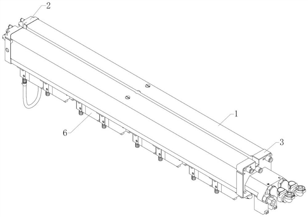
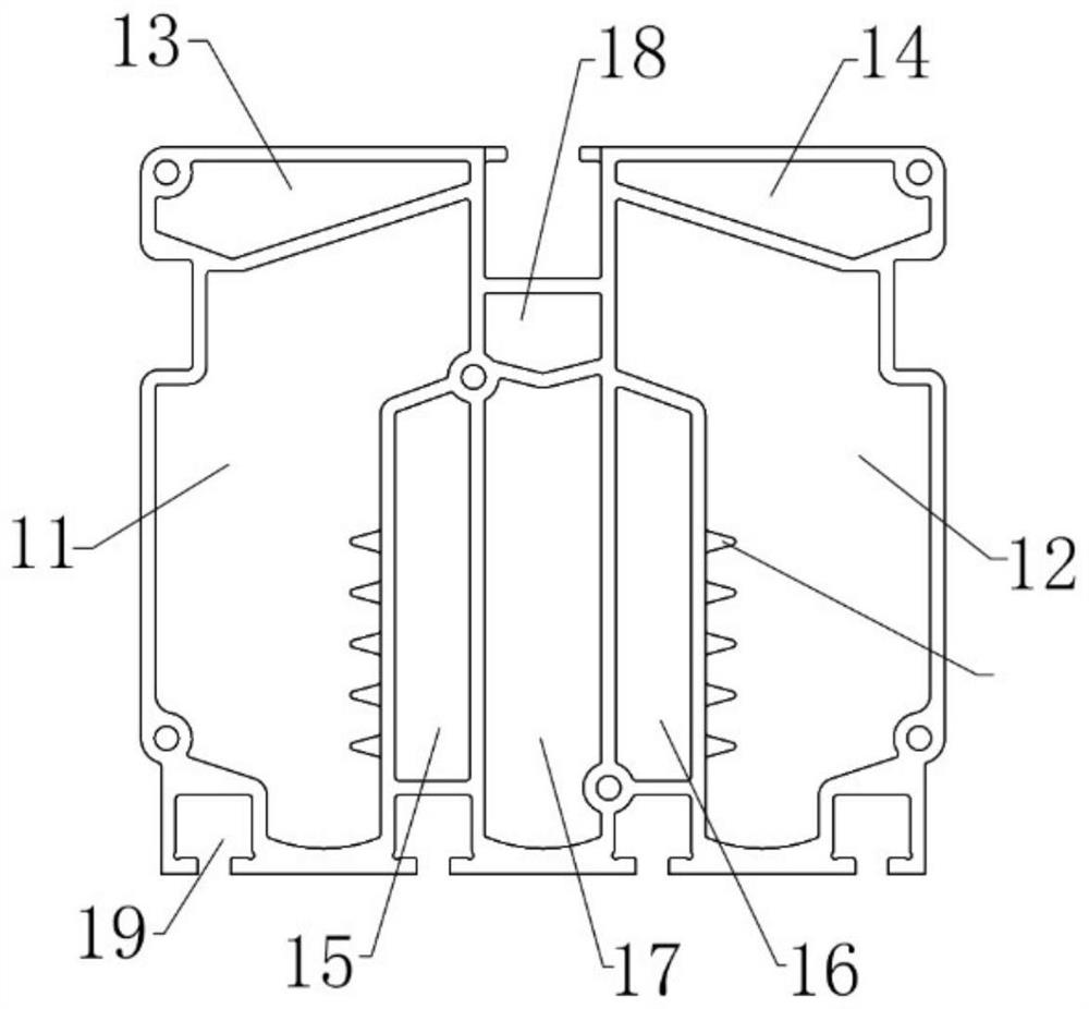
[0061] refer to figure 1 and figure 2 As shown, a secondary ink cartridge for an inkjet printer is improved in that it includes an ink cartridge body 1, a rear end cover 2 and a front end cover 3 that are respectively sealed and closed with the ink cartridge body 1, and the ink cartridge body 1 There are ink supply chambers 11 and return ink chambers 12 respectively located on the left and right sides thereof, the bottoms of the ink supply chamber 11 and the return ink chamber 12 are respectively provided with several ink holes, and the ink supply chamber 11 and the ink return chamber 12 are respectively provided with ink holes. The liquid level sensors used to detect the amount of ink in the ink chamber are respectively provided in the described backflow ink chamber 12, the top of the described ink supply chamber 11 is provided with a negative pressure chamber I13 communicating with it, and the top of the described backflow ink chamber 12 is provided with There is a negativ...

Embodiment 2

[0066] On the basis of Embodiment 1, the ink return chamber 12 communicates with the main ink tank of the printer, the ink return chamber 12 communicates with one end of the degasser, and the other end of the degasser communicates with the supply The ink chambers 11 are connected.

[0067] In this embodiment, the ink in the main ink tank is continuously pumped into the return ink chamber 12 by the pump, and the ink pumped into the return ink chamber 12 by the main ink tank is inevitably mixed with air bubbles, and the ink mixed with air bubbles enters the printing ink chamber. The nozzle is prone to empty spraying during printing, which affects the printing quality. Therefore, another circulation path is set between the return ink chamber 12 and the ink supply chamber 11. This circulation path is used to remove the ink entering the ink supply chamber 11. The air bubbles in the return ink chamber 12 flow into the degassing device under the action of the pump, and enter the ink ...

Embodiment 3

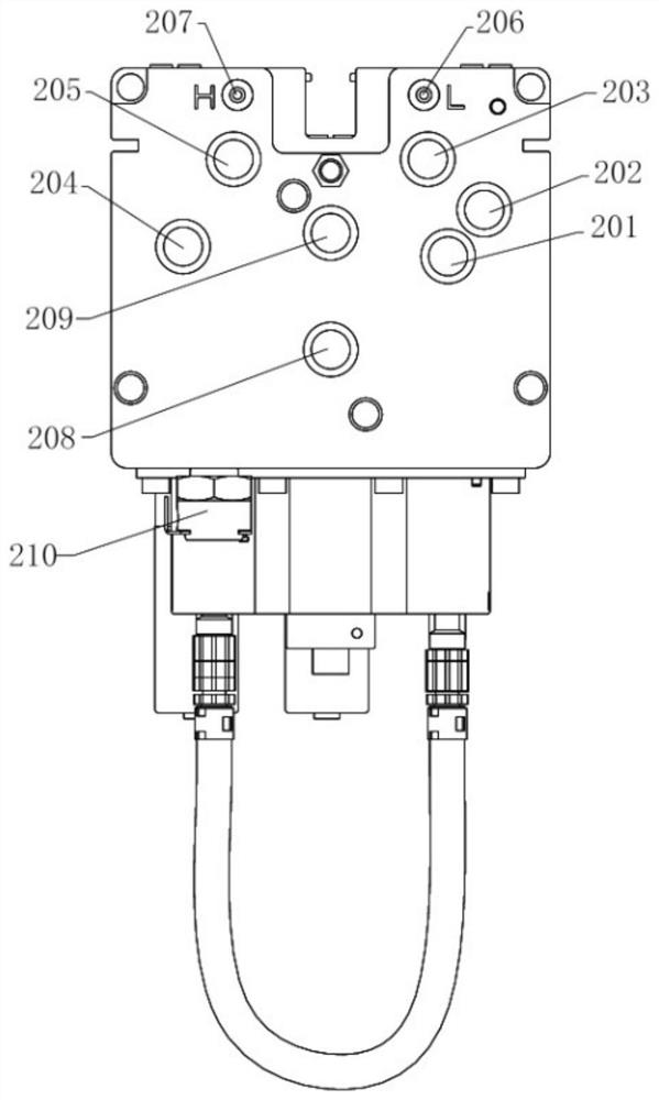
[0069] On the basis of embodiment 2, with reference to Figure 3 to Figure 8 As shown, the liquid level sensors in the return ink chamber 12 include a low liquid level sensor II204 and a high liquid level sensor II205.

[0070] Further, the low liquid level sensor II204 and the high liquid level sensor II205 are installed on the rear end cover 2 and placed in the ink return chamber 12 .

[0071] Further, the ink return chamber 12 is provided with an ink pipe II5, and the ink pipe II5 is installed between the front end cover 3 and the rear end cover 2, perpendicular to the front end cover 3 and lower than the Low level sensor II204, refer to Figure 11 As shown, the bottom of the ink tube II5 is provided with several through holes II.

[0072] Further, an ink inlet joint I301 is installed on the outside of the front end cover 3, and an ink inlet hole 311 is arranged on the inside of the front end cover 3, and the ink inlet hole 311 communicates with the ink inlet connector I3...


PUM


Abstract

The secondary ink box comprises an ink box body, a rear end cover and a front end cover, the rear end cover and the front end cover are sealed and covered with the ink box body, an ink supply cavity and a backflow ink cavity which are located on the left side and the right side of the ink box body respectively are formed in the ink box body, and a plurality of ink through holes are formed in the bottom of the ink supply cavity and the bottom of the backflow ink cavity respectively. The ink supply cavity and the backflow ink cavity are each internally provided with a liquid level sensor used for detecting the amount of ink in the ink cavity, a negative pressure cavity I communicated with the ink supply cavity is formed above the ink supply cavity, and a negative pressure cavity II communicated with the backflow ink cavity is formed above the backflow ink cavity. The secondary ink box for the ink-jet printer is ingenious in design and has the beneficial effects that ink precipitation is prevented, bubbles are effectively removed, the printing stability is high, the constant-temperature effect is good, and the reliability is high.

Description

technical field [0001] The invention relates to the technical field of inkjet printing equipment, in particular to a secondary ink box for an inkjet printer. Background technique [0002] The printing trolley of the inkjet printer is equipped with a secondary ink cartridge, which is also called a secondary ink cartridge. Ink flows from the main ink tank to the secondary ink tank, and then the secondary ink tank supplies ink to each nozzle. In order to ensure the normal supply of ink, a liquid level sensor is often provided on the secondary ink cartridge to detect the amount of ink in the ink cartridge, so that the ink supply can be supplied in time when the ink cartridge is short of ink or the ink supply is sufficient; the ink of the secondary ink cartridge The negative pressure system and positive pressure system also need to be connected to the chamber. The negative pressure system is used to adjust the negative pressure value in the ink chamber to ensure the normal ink s...

Claims


Application Information

Patent Timeline
Patent Type & Authority Applications(China)
IPC IPC(8): B41J2/175B41J2/19B41J2/165
CPCB41J2/17503B41J2/17556B41J2/17513B41J2/19B41J2/17566B41J2/17506B41J2/16552
Inventor 单健王家远闫峂脱占贺单川
Owner BEIJING ZHONGDIAN YUANDE TECH CO LTD
Why Eureka
Try Eureka