High-pressure water cooling resistor

A water-cooled resistor, high-voltage technology, applied in resistors, resistor parts, resistor cooling/heating/ventilation devices, etc., can solve the problems of low cooling water level, prone to electric shock accidents, damage and aging of sealing rings, etc. The effect of improving airtightness

Inactive Publication Date: 2021-06-18
李志强
View PDF8 Cites 0 Cited by
  • Summary
  • Abstract
  • Description
  • Claims
  • Application Information

AI Technical Summary

Problems solved by technology

[0003] When using resistors, the heat exchange is carried out directly with the cooling water through the resistance material; in order to achieve the purpose of heat dissipation, most of the cooling water flows directly through the conduit, because the diameter of the conduit for the water is small, As a result, the water level of the cooling water flowing into the conduit is low, and the heat inside the resistor cannot be effectively dissipated, and the cooling water flows into the resistor, because the sealing ring between the conduit and the resistor will be damaged and aged due to high temperature. The cooling water will flow and penetrate into the resistor, which will affect the operation of the resistor and cause electric shock accidents

Method used


Image

  • High-pressure water cooling resistor
  • High-pressure water cooling resistor
  • High-pressure water cooling resistor

Examples


Embodiment 1

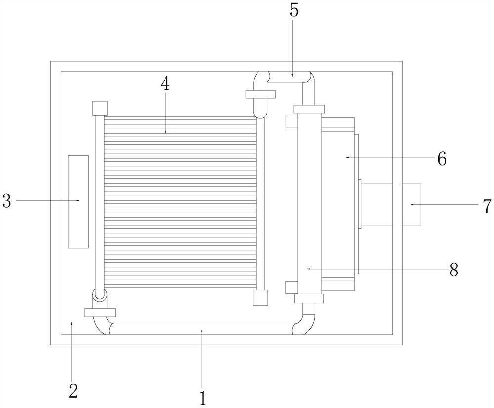
[0030] See figure 1 The present invention provides a technical solution: a high-pressure water-free resistor, which includes a first conduit 1, a casing 2, a wiring electrode plate 3, a water-cooled resistor 4, a second conduit 5, a heat sink 6, an inward, and an in-force. The processing apparatus 8 is turned on with the water-cooled resistor 4 phase and the other end is turned on with the processing apparatus 8, and the water-cooled resistor 4 is fixed inside the casing 2, the water-cooled resistor 4 and a wiring electrode plate. 3 is connected by a wire, the water-cooled resistor 4 is turned on from one end of the first conduit 1 and the second conduit 5, and the second conduit 5 is connected to the first conduit 1, the processing device 8 and The heat sink 6 is connected, and the heat sink 6 is turned on with the inlet and exit 7.

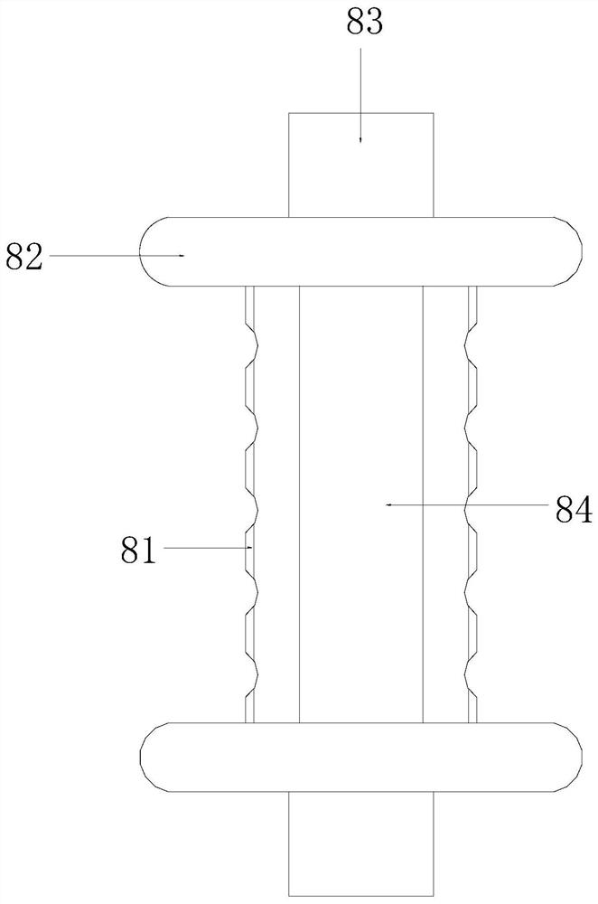
[0031] See figure 2 The processing apparatus 8 includes a conductive assembly 81, a seal 82, an interface 83, a cyclone 84, and the conductive asse...

Embodiment 2

[0040] See figure 1 The present invention provides a technical solution: a high-pressure water-free resistor, which includes a first conduit 1, a casing 2, a wiring electrode plate 3, a water-cooled resistor 4, a second conduit 5, a heat sink 6, an inward, and an in-force. The processing apparatus 8 is turned on with the water-cooled resistor 4 phase and the other end is turned on with the processing apparatus 8, and the water-cooled resistor 4 is fixed inside the casing 2, the water-cooled resistor 4 and a wiring electrode plate. 3 is connected by a wire, the water-cooled resistor 4 is turned on from one end of the first conduit 1 and the second conduit 5, and the second conduit 5 is connected to the first conduit 1, the processing device 8 and The heat sink 6 is connected, and the heat sink 6 is turned on with the inlet and exit 7.

[0041] See figure 2 The processing apparatus 8 includes a conductive assembly 81, a seal 82, an interface 83, a cyclone 84, and the conductive asse...


PUM


Abstract

The invention discloses a high-pressure water cooling resistor which structurally comprises a first pipeline, a box body, a wiring electrode plate, a water cooling resistor, a second pipeline, a radiator, an inlet/outlet and a processing device. When the high-pressure water cooling resistor is used, after water flow enters a threaded pipe, a spiral water path is formed in the threaded pipe due to inertia, and the speed of the water flow is increased; cooling liquid can quickly flow into the water cooling resistor through the threaded pipe to circularly flow, hot air on the threaded pipe is blocked through the heat insulation layer, and the threaded pipe is sealed by matching a rubber cushion and a spiral tightening strip with a conduction port, so that the rubber cushion and the spiral tightening strip are in a closed state, and the cooling liquid in the threaded pipe is prevented from flowing and permeating into the resistor; and the water cooling resistor is protected, so that the water cooling resistor can operate stably.

Description

Technical field [0001] The present invention relates to the field of resistance, and more particularly to a high pressure water-free resistor. Background technique [0002] With the rapid development of electricity electronic technology, high-power power electronics continues to emerge, water-cooled resistors are a energy consumption component, and water-cooled resistors are used in high-power circuits, and they have heat absorption. The cooling water is blocked by the sealing element, and when the resistor is used, there is a need to improve: [0003] When performing the use resistor, heat exchange directly by the resistive material and the cooling water; in order to achieve the dissipation purpose, the cooling water is in the flow process, and most of them are directly venting through the catheter, because the tube diameter of the water is smaller. The cooling water level inside the inflowing catheter is low, and the heat inside the resistor cannot be effectively dispersed, and...

Claims


Application Information

Patent Timeline
Patent Type & Authority Applications(China)
IPC IPC(8): H01C1/08H01C1/082
CPCH01C1/08H01C1/082
Inventor 许淑环
Owner 李志强
Why Eureka
Try Eureka