Overhead operation platform arranged on vehicle crane jib
A technology for aerial work platforms and truck cranes, applied in the direction of hoisting devices, etc., can solve the problems of no suitable aerial work vehicles, failure to meet technical requirements, time not allowed, etc., and achieve the effects of improving efficiency, convenient adjustment, and enhancing smoothness.
- Summary
- Abstract
- Description
- Claims
- Application Information
AI Technical Summary
Problems solved by technology
Method used
Image

Examples
Embodiment Construction
[0029] Below in conjunction with accompanying drawing and specific embodiment the present invention is described in further detail:
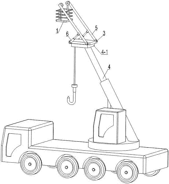
[0030] The invention discloses an aerial work platform arranged on the boom of a truck crane. The aerial work platform is arranged on the lifting lug at the top of the boom of the truck crane. Based on the existing truck crane, the truck crane has the function of the aerial work platform. effect.
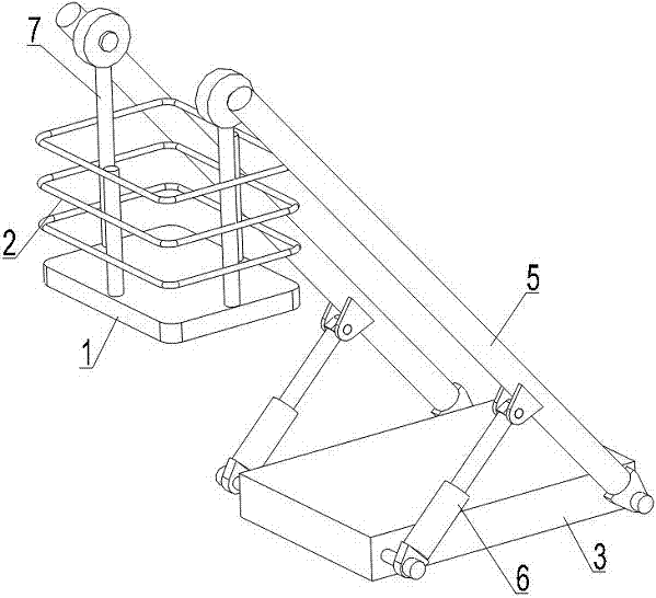
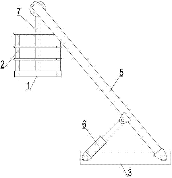
[0031] The high-altitude work platform of the present invention is arranged on the lug 4-1 at the top of the boom 4 of the truck crane. The high-altitude work platform includes a work platform 1 provided with a guardrail 2. The work platform 1 generally uses a rectangular steel plate, and the specific size is selected according to needs. , the length is generally 1.6-2.0m, and the width is generally 1.0-1.4m. A guardrail 2 is arranged on the work platform 1 to ensure the safety of the staff, and the guardrail also has the function of connecting a saf...
PUM
 Abstract
Description
Claims
Application Information
 - R&D
- Intellectual Property
- Life Sciences
- Materials
- Tech Scout
- Unparalleled Data Quality
- Higher Quality Content
- 60% Fewer Hallucinations
Browse by: Latest US Patents, China's latest patents, Technical Efficacy Thesaurus, Application Domain, Technology Topic, Popular Technical Reports.
© 2025 PatSnap. All rights reserved.Legal|Privacy policy|Modern Slavery Act Transparency Statement|Sitemap|About US| Contact US: help@patsnap.com