
Device and method for preparing optical fiber preform base material by tube outside method

An optical fiber preform and base material technology, which is applied in the field of optical fiber manufacturing, can solve the problems of large deviation in height detection at the bottom surface of the powder rod core layer, large errors in the vertical direction, affecting the quality parameters of the core layer, etc., and achieve detection accuracy. The effect of improving, reasonable and simple setting, and good quality of processed products

Inactive Publication Date: 2018-01-05
YANGTZE OPTICAL FIBRE & CABLE CO LTD
View PDF7 Cites 3 Cited by
  • Summary
  • Abstract
  • Description
  • Claims
  • Application Information

AI Technical Summary

Problems solved by technology

Since the emission of the detection laser is along the horizontal direction, while the formation and growth process of the powder rod is along the vertical direction, the two directions differ by 90°. In actual use, there is a certain error in the installation of the laser detector, so the level of the detection laser There will also be some errors in the degree. Since the laser detector is installed outside the reaction chamber and has a certain length from the detection point, a certain angle of inclination in the horizontal direction will cause a large error in the vertical direction, making the core layer of the powder rod There is a large deviation in the detection of the height where the bottom surface is formed, such as image 3 As shown, if the distance from the laser measuring instrument to the formation of the core layer is L, if the deviation angle in the horizontal direction is θ, the longitudinal deviation along the growth direction of the core layer of the powder rod is H 1 , H 1 =L×sinθ, when L is large, there will be a large deviation, and the deviation in height is related to the jet landing point of the jet flame of the core layer blowtorch, resulting in a decrease in control accuracy, thereby affecting a series of core layer shape, size, density, etc. Quality parameters, also related to the stability of growth during deposition, these will determine the quality of deposited powder sticks
[0003] U.S. Patent US20120103023A1 discusses the use of CCD to obtain the core-cladding image in the powder rod deposition, so as to measure the core-cladding ratio to produce the initial product with a stable core-cladding ratio. However, the problem with this method is that the boundary is not well defined. Precise, which affects control during powder stick deposition

Method used


Image

  • Device and method for preparing optical fiber preform base material by tube outside method
  • Device and method for preparing optical fiber preform base material by tube outside method
  • Device and method for preparing optical fiber preform base material by tube outside method

Examples


Embodiment Construction

[0020] The present invention will be further described below in conjunction with embodiment and accompanying drawing.

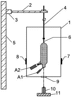
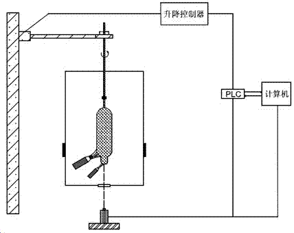
[0021] Embodiments of the device of the present invention are figure 1 , 2 Shown, comprise vertical tower frame 5, vertical tower frame vertical direction is equipped with liftable guide rail, connects lifting cantilever frame 2 by elevating seat 3 on the guide rail, and lifting cantilever frame front end installs mobile rotating boom 4, moves The bottom of the rotating boom 4 is fixed with a glass target rod 6 used for deposition, and the bottom of the moving rotating boom is correspondingly installed with a reaction chamber 1 for deposition, and the moving rotating boom extends into the reaction chamber. There is a core blowtorch A1 and a cladding blowtorch A2, the nozzles of the core blowtorch and the cladding blowtorch are inclined upwards, wherein the elevation angle of the core blowtorch is 50°, and the elevation angle of the cladding blowtorch is 40°...


PUM


Abstract

The invention relates to a device and a method for preparing an optical fiber preform base material by a tube outside method. The device comprises a reaction chamber, wherein a movable rotary suspender is arranged in the upper part of the reaction chamber, and an upper cladding blowtorch and a lower core blowtorch are separately arranged corresponding to the movable rotary suspender on one side inthe lower part of the reaction chamber, and are used for forming a core and a cladding of an optical fiber preform base material by deposition. The device is characterized in that a core range finderis arranged under a position where the core is formed outside the reaction chamber, the output end of the core range finder is connected to a PLC (programmable logic controller) unit and a computer,and the PLC unit is connected to the computer, and is connected to a lifting controller, so that the core range finder and the lifting controller can generate feedback. According to the device and themethod, the precision of powder rod core detection is increased, and therefore deposition diameters of the core and the cladding can be accurately and dynamically controlled, thus increasing the processing quality of the optical fiber preform base material; and the device and the method have the advantages of reasonable and simple arrangement, high automation degree, convenience in operation, rapid and reliable feedback mechanism and high stability, and are suitable for mass production.

Description

technical field [0001] The invention relates to a device and method for preparing an optical fiber preform base material by an external method, in particular to a device and a method for preparing an optical fiber preform base material by a VAD method, and belongs to the technical field of optical fiber manufacturing. Background technique [0002] In the VAD preparation of the optical fiber preform base material device, most of the laser measuring instruments are used to detect the growth and core diameter of the deposited mandrel. The laser measuring instruments are mostly placed outside the reaction chamber. The height of the core layer formation is the same, the purpose is to control the height of the core layer formation, so that the height of the core layer formation and the injection height of the core layer torch remain constant, thereby ensuring the processing quality of the core layer deposition. Since the emission of the detection laser is along the horizontal dire...

Claims


Application Information

Patent Timeline
IPC IPC(8): C03B37/014
Inventor 冯正鹏黄利伟王瑞春顾立新刘善沛张宏胜雷汉林秦爱民王俊陈刚
Owner YANGTZE OPTICAL FIBRE & CABLE CO LTD
Learn More