Turning transmission gear of lapper fan

A transmission device and lapping machine technology, applied in the field of cotton textile machinery, can solve the problems of increased friction of the transmission belt, unguaranteed product quality, increased consumption of machine parts, etc., achieve stable negative pressure airflow, eliminate hidden dangers of production quality, The effect of saving machine materials

Inactive Publication Date: 2018-01-05
JIHUA 3542 TEXTILE CO LTD
View PDF0 Cites 0 Cited by
  • Summary
  • Abstract
  • Description
  • Claims
  • Application Information

AI Technical Summary

Problems solved by technology

Due to the cross installation of the transmission belt, the friction of the transmission belt increases, causing the shaft of the beater and the fan to heat up. At the same time, the transmission belt is severely worn, which increases the consumption of machine parts, the product quality cannot be guaranteed, and affects the normal operation of the equipment.

Method used


Image

  • Turning transmission gear of lapper fan
  • Turning transmission gear of lapper fan

Examples


Embodiment Construction

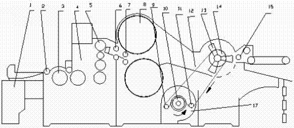
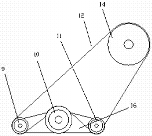
[0011] like figure 1 , figure 2 As shown, the present invention includes a cotton roll trolley 1, a cotton roll stick 2, a roll roller 3, a pressing roller 5, an anti-sticking roller 6, a cotton output roller 7, an upper and lower dust cage 8, a comprehensive beater 13, and a balance cotton device 15 , guide wheel support 16, fan base 17; described balance cotton device 15 is connected with comprehensive beater 13 entrances, and comprehensive beater 13 outlets are connected with upper and lower dust cages 8, and the cotton layer adsorbed on the upper and lower dust cages 8 passes through the cotton rollers successively 7. The anti-sticking roller 6 is connected with the compression roller 5, and the exit of the compression roller 5 is connected with the roll roller 2 through the roll roller 3 in turn, and the cotton roll stick 2 after winding the cotton roll is pushed onto the cotton roll trolley 1 . The beater pulley 14 of the comprehensive beater 13 is connected with the ...


PUM


Abstract

The utility model relates to a direction-changing transmission device for a cotton roll fan of a lapping machine, which relates to the technical field of cotton textiles. The balance cotton device is connected to the inlet of the integrated beater, and the outlet of the integrated beater is connected to the upper and lower dust cages, and the cotton layers adsorbed on the upper and lower dust cages pass through the cotton in turn The rollers, anti-sticking rollers are connected with the pressing rollers, and the exits of the pressing rollers are connected successively through the roll forming rollers, the cotton rolling sticks and the cotton lap trolley; The front belt guide wheel and the rear belt guide wheel, the front belt guide wheel and the rear belt guide wheel are installed on the guide wheel bracket, the guide wheel bracket is connected with the frame through the fan seat, and the front belt guide wheel and the rear belt guide wheel are respectively It is equipped to prevent the fan belt from running off the side of the wheel. The fan of the invention has flexible rotation and stable negative pressure airflow, solves the problem of fan belt cross wear, ensures stable production of equipment, simple structure, safe operation, can effectively save machine materials, and ensure normal production.

Description

technical field [0001] The invention relates to the technical field of cotton textile machinery, in particular to a direction-changing transmission device for a fan of a lapping machine. Background technique [0002] In cotton textile production, the blower fan of the A076 lap machine in the existing cleaning process is driven by the belt pulley of the beater, and the raw materials that have been loosened by the beater are adsorbed to the upper and lower dust cages by the negative pressure airflow generated by the fan, and compressed The roller presses the cotton layer, and then winds it on the cotton lap bar through the lap forming roller to make a cotton lap of a certain specification for use in the next process. According to the design of the production process, when the fan pipe is installed towards the rear of the machine, the running direction of the beater and the fan of the A076 coiling machine are two different directions. The beater rotates clockwise, and the fan r...

Claims


Application Information

Patent Timeline
Patent Type & Authority Applications(China)
IPC IPC(8): D01G25/00
Inventor 史廷勇王建华
Owner JIHUA 3542 TEXTILE CO LTD
Why Eureka
Try Eureka