Environment-friendly cooling fan
A cooling fan, environmentally friendly technology, applied in the direction of space heating and ventilation, heating and ventilation hood/cover, heating method, etc.
- Summary
- Abstract
- Description
- Claims
- Application Information
AI Technical Summary
Problems solved by technology
Method used
Image
Examples
Embodiment 1
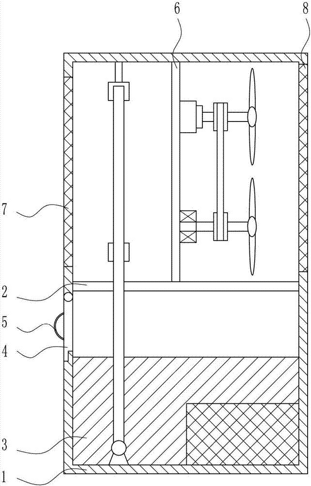
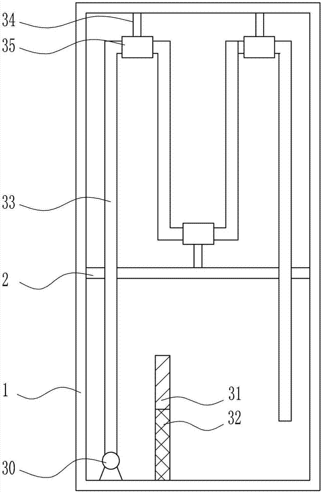
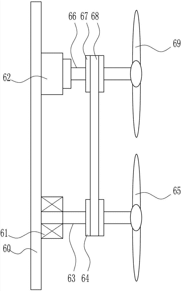
[0030] An environmentally friendly cooling fan, such as Figure 1-5As shown, it includes a box body 1, a partition plate 2, a water circulation device 3, a box door 4, a handle 5, a blower device 6, a second net plate 7 and a third net plate 8, and the left and right walls of the middle part of the box body 1 There is a partition plate 2 between them, and a water circulation device 3 is provided at the inner bottom of the box body 1. The water circulation device 3 passes through the partition plate 2, and the lower part of the left wall of the box body 1 is rotatably connected with a door 4, and the box door 4 is located on the partition plate 2. Below, the left side of the box door 4 is provided with a handle 5, the top of the partition plate 2 is provided with a blowing device 6, and the blowing device 6 is located at the upper right of the water circulation device 3, and the upper left side of the casing 1 is provided with a second mesh plate 7, the second The net plate 7 i...
Embodiment 2
[0032] An environmentally friendly cooling fan, such as Figure 1-5 As shown, it includes a box body 1, a partition plate 2, a water circulation device 3, a box door 4, a handle 5, a blower device 6, a second net plate 7 and a third net plate 8, and the left and right walls of the middle part of the box body 1 There is a partition plate 2 between them, and a water circulation device 3 is provided at the inner bottom of the box body 1. The water circulation device 3 passes through the partition plate 2, and the lower part of the left wall of the box body 1 is rotatably connected with a door 4, and the box door 4 is located on the partition plate 2. Below, the left side of the box door 4 is provided with a handle 5, the top of the partition plate 2 is provided with a blowing device 6, and the blowing device 6 is located at the upper right of the water circulation device 3, and the upper left side of the casing 1 is provided with a second mesh plate 7, the second The net plate 7 ...
Embodiment 3
[0035] An environmentally friendly cooling fan, such as Figure 1-5 As shown, it includes a box body 1, a partition plate 2, a water circulation device 3, a box door 4, a handle 5, a blower device 6, a second net plate 7 and a third net plate 8, and the left and right walls of the middle part of the box body 1 There is a partition plate 2 between them, and a water circulation device 3 is provided at the inner bottom of the box body 1. The water circulation device 3 passes through the partition plate 2, and the lower part of the left wall of the box body 1 is rotatably connected with a door 4, and the box door 4 is located on the partition plate 2. Below, the left side of the box door 4 is provided with a handle 5, the top of the partition plate 2 is provided with a blowing device 6, and the blowing device 6 is located at the upper right of the water circulation device 3, and the upper left side of the casing 1 is provided with a second mesh plate 7, the second The net plate 7 ...
PUM
 Abstract
Description
Claims
Application Information
 - R&D
- Intellectual Property
- Life Sciences
- Materials
- Tech Scout
- Unparalleled Data Quality
- Higher Quality Content
- 60% Fewer Hallucinations
Browse by: Latest US Patents, China's latest patents, Technical Efficacy Thesaurus, Application Domain, Technology Topic, Popular Technical Reports.
© 2025 PatSnap. All rights reserved.Legal|Privacy policy|Modern Slavery Act Transparency Statement|Sitemap|About US| Contact US: help@patsnap.com


