Eureka AIR delivers breakthrough ideas for toughest innovation challenges, trusted by R&D personnel around the world.

Continuous multi-layer dryer for plywood and method using same

A dryer and plywood technology, which is applied in the joining of wooden veneers, wood processing appliances, manufacturing tools, etc., can solve the problems of inability to meet production needs, reduce production efficiency, low drying efficiency, etc., to improve the degree of automated production and The effect of production efficiency, improving utilization rate and saving space

Active Publication Date: 2018-01-09
HESHAN JIDING MACHINERY CO LTD
View PDF10 Cites 0 Cited by
  • Summary
  • Abstract
  • Description
  • Claims
  • Application Information

AI Technical Summary

Problems solved by technology

Among them, after the board has undergone multiple processes such as scraping putty ash on the surface of the board to fill the gaps, the board will become very wet, and the wet board needs to be dried to release the internal moisture in time before subsequent processing can be carried out. However, the traditional board The drying method is to use spacers to separate the wet plates separately, and then stack them together and pull them into the drying room before drying. After drying, the plates and spacers need to be separated, which is not only cumbersome, time-consuming and laborious. Moreover, the drying efficiency is low and the floor area is large
[0003] At present, there are still some plywood dryers on the market. These dryers are basically single-layer or double-layer roller dryers or mesh belt dryers. The hot air blower can only be used, the heat loss is fast, the energy consumption is high, the overall equipment is expensive and the number of drying plates is effective, which greatly reduces the production efficiency and cannot meet the current growing production demand

Method used


Image

  • Continuous multi-layer dryer for plywood and method using same
  • Continuous multi-layer dryer for plywood and method using same
  • Continuous multi-layer dryer for plywood and method using same

Examples


Embodiment Construction

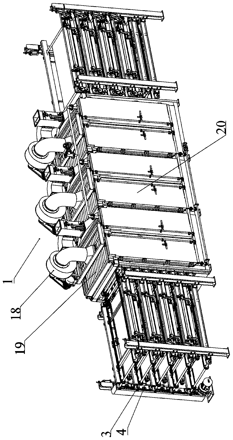
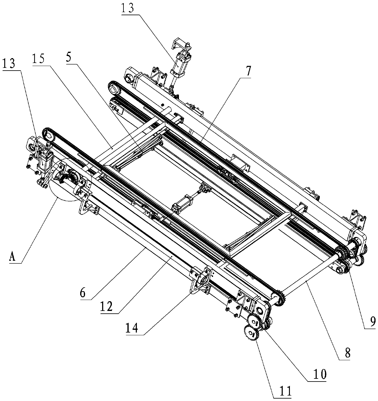
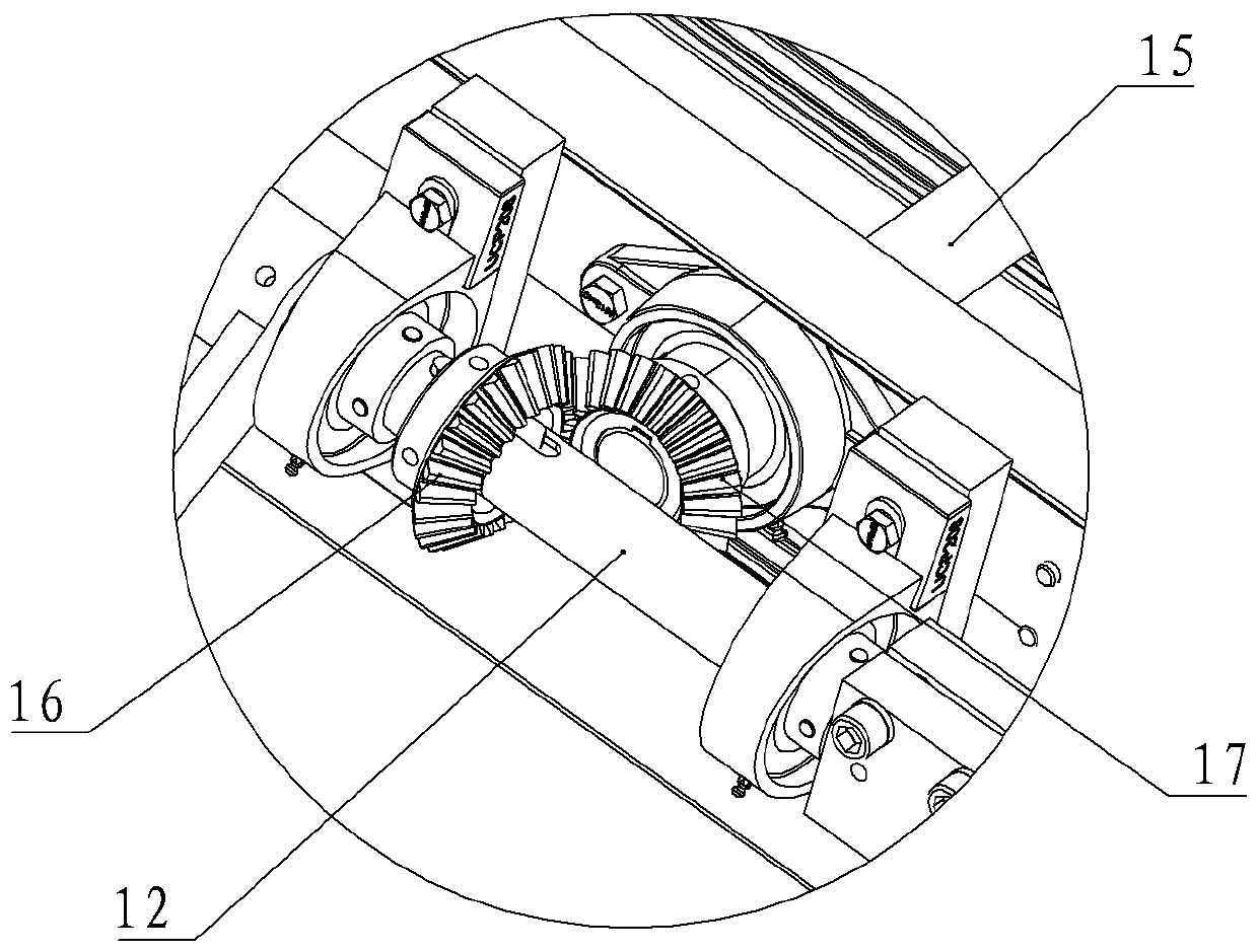
[0023] refer to Figure 1 to Figure 2 , plywood continuous multi-layer drying machine, comprising a dryer 1, a multi-layer translation conveyor belt 2 is provided in the dryer 1, and a lifting conveying mechanism 3 and a clamping mechanism 3 are respectively provided at both ends of the multi-layer translation conveyor belt 2 The conveying mechanism 4, the upper layer of the lifting conveying mechanism 3 is correspondingly provided with a clamping conveying mechanism 4; the lifting conveying mechanism 3 is at least composed of a lifting frame 5 and a driving mechanism of the lifting frame 5, and the driving mechanism drives the lifting frame 5 to the clamping conveying mechanism 4 positions move up and down; the clamping and conveying mechanism 4 is at least composed of a pair of clamping arms 6 that can be opened and closed, and an opening and closing drive mechanism that drives the clamping arms 6 to open and close. By using the lifting conveying mechanism 3 and the clamping...


PUM


Abstract

The invention discloses a continuous multi-layer dryer for plywood and a method using the same. The continuous multi-layer dryer for the plywood comprises a dryer body in which a plurality of layers of horizontal moving conveying belts are arranged; the two ends of the layers of horizontal moving conveying belts are each provided with a lifting conveying mechanism and a clamping conveying mechanism; and the clamping conveying mechanisms are correspondingly arranged on the upper layers of the lifting conveying mechanisms. The method for using the dryer includes the steps that boards are liftedto the upper layer through the lifting conveying mechanisms, the boards are clamped and conveyed into the dryer through the clamping conveying mechanisms to continue to be dried, the above action is repeated ceaselessly, and three-dimensional reciprocating and circulating drying of the boards in the dryer is achieved. By means of continuous multi-layer dryer for the plywood, the boards can reach the optimum drying effect, meanwhile, the space utilizing rate is increased to an extremely large limit, space is saved, the energy consumption is low, and the automatic production degree and the production efficiency are improved.

Description

technical field [0001] The invention relates to the technical field of plate drying equipment, in particular to a plywood continuous multi-layer dryer. Background technique [0002] The production of plywood or plywood is to cut the wood raw material into boards and then go through multiple processes, and the multi-layer boards are glued and laminated to form. Among them, after the board has undergone multiple processes such as scraping putty ash on the surface of the board to fill the gaps, the board will become very wet, and the wet board needs to be dried to release the internal moisture in time before subsequent processing can be carried out. However, the traditional board The drying method is to use spacers to separate the wet plates separately, and then stack them together and pull them into the drying room before drying. After drying, the plates and spacers need to be separated, which is not only cumbersome, time-consuming and laborious. Moreover, the drying efficien...

Claims


Application Information

Patent Timeline
Patent Type & Authority Applications(China)
IPC IPC(8): B27D1/08
Inventor 熊云斌
Owner HESHAN JIDING MACHINERY CO LTD
Why Eureka
Eureka Blog
Learn More