Combined mould and forming method used for bulged bar prefabricated part forming

A technology of prefabricated components and molding methods, which is applied to manufacturing tools, ceramic molding machines, etc., can solve the problems of high construction strength, difficult demoulding, and easy leakage of molding die, so as to achieve long service life, reduced demoulding difficulty, and easy demoulding. The effect of mold efficiency improvement

Inactive Publication Date: 2018-01-09
CHANGSHA BROAD HOMES IND GRP CO LED
View PDF7 Cites 4 Cited by
  • Summary
  • Abstract
  • Description
  • Claims
  • Application Information

AI Technical Summary

Problems solved by technology

[0005] The technical problem solved by the invention is that the forming mold of the reinforced concrete is easy to leak grout, it is difficult to demould, and the construction strength is high

Method used


Image

  • Combined mould and forming method used for bulged bar prefabricated part forming
  • Combined mould and forming method used for bulged bar prefabricated part forming
  • Combined mould and forming method used for bulged bar prefabricated part forming

Examples


Embodiment Construction

[0038] The following will refer to the attached figure 1 to attach Figure 9 The present invention will be described in detail in combination with examples. It should be noted that, in the case of no conflict, the embodiments of the present invention and the features in the embodiments can be combined with each other. For the convenience of description, if the words "up", "down", "left" and "right" appear in the following, it only means that the directions of up, down, left and right are consistent with the drawings themselves, and do not limit the structure.

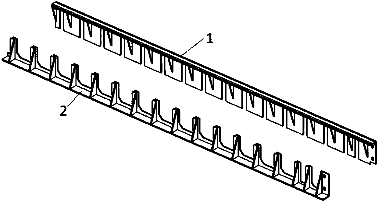
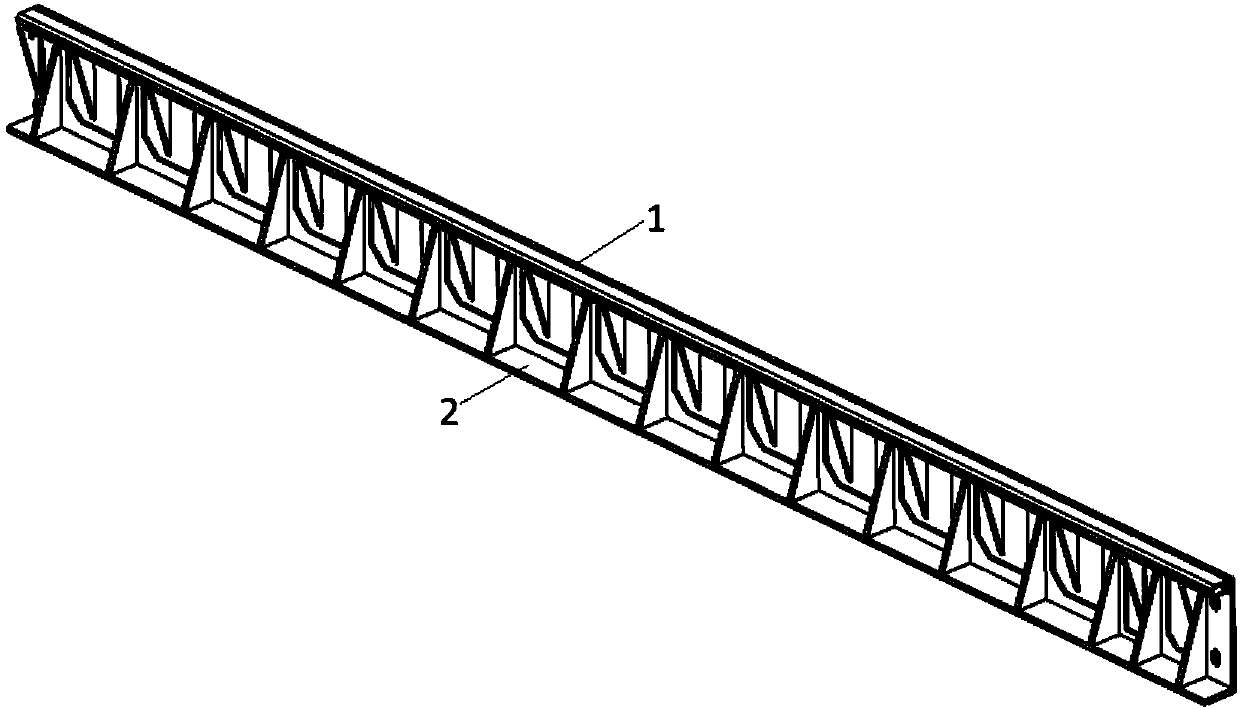
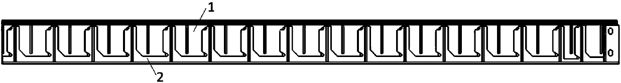
[0039] A combined mold for molding prefabricated components, including a first formwork 1 and a second formwork 2, the first formwork 1 is provided with a groove 101 perpendicular to the length direction of the first formwork, and the groove 101 is connected to the first formwork 1 The bottom side of the second template 2 is provided with a bar 201 that is misplaced with the groove 101, and one side of the bar 201 is ...


PUM


Abstract

The invention relates to a combined mould used for bulged bar prefabricated part forming. The combined mould comprises a first molding board and a second molding board, wherein slots perpendicular tothe length direction of the first molding board are formed in the first molding board; the slots communicate with the bottom side of the first molding board; baffle strips which are staggered with theslots are arranged on the second molding board; two notches for placing reinforcing steel bars are formed in one side of each baffle strip; the first molding board is combined with the second moldingboard to form an integrated molding board; and a first bar penetrating hole and a second bar penetrating hole for allowing the reinforcing steel bars to pass through are formed between each slot andthe corresponding baffle strip. After being combined, the mould is good in sealing property, and the holes for just allowing the reinforcing steel bars to pass through are formed in the formed integrated molding board, so that occurrence of leaked slurry is greatly reduced in comparison with waist-shaped holes in the prior art, building materials are favorably saved, and a prefabricated componentwith uniform components is obtained; molding and de-molding are convenient, de-molding difficulty is reduced, and de-molding efficiency is greatly improved; acting force on each molding board is relatively small in a molding process and a de-molding process; and moreover, structural strength of the molding boards is high, so that the molding boards are not liable to damage, and using and maintaining cost of the mould is reduced.

Description

technical field [0001] The invention relates to a combined mold and a molding method for molding prefabricated components with ribs, and belongs to the technical field of concrete moulds. Background technique [0002] Prefabricated concrete components are building components prefabricated in factories with concrete as the basic material, including prefabricated building components such as walls, beams, panels, and columns. Since prefabricated components need to be connected with other components to form strength, protruding steel bars are often reserved on the outer surface of prefabricated components. These reserved steel bars are called ribs because they protrude on the outer surface of the prefabricated components. When the ends of the two ribs of the prefabricated part are connected by steel bars to form a closed structure, the ribs at this time are called stirrups. [0003] Standard concrete prefabricated components are generally cuboid structures, which are hexahedro...

Claims


Application Information

Patent Timeline
Patent Type & Authority Applications(China)
IPC IPC(8): B28B7/24B28B7/00B28B1/04B28B23/02
Inventor 张剑王雅明徐雷朱彦哲
Owner CHANGSHA BROAD HOMES IND GRP CO LED
Why Eureka
Try Eureka