
Hydraulic control system and hinge dam assembly

A hydraulic control system and hinge dam technology, applied in the field of movable dams, can solve problems such as easy to get stuck in floating objects, high flow rate, and unable to control the synchronous action of hydraulic cylinders.

Pending Publication Date: 2018-01-09
CHINA INST OF WATER RESOURCES & HYDROPOWER RES +1
View PDF0 Cites 1 Cited by
  • Summary
  • Abstract
  • Description
  • Claims
  • Application Information

AI Technical Summary

Problems solved by technology

[0004] There are often a lot of floating objects on the water surface in the river. When the single leaf hinge dam is raised, the floating objects are easily stuck between the two hinge dams, which will cause unsafe factors for the operation of the hinge dam.
At the same time, since the shape of the cross-section of the river channel is trapezoidal and the flow velocity of the water is relatively large, the impact force produced by the water in the river channel on each hinge dam is also different, which makes the loads borne by each hydraulic cylinder different.
[0005] In the related technology, the simultaneous lifting and lowering of each hinge dam is controlled by installing a diversion and confluence valve in the hydraulic control circuit. However, when a diversion and confluence valve is used, although the diversion and confluence valve can enforce a diversion of the flow of the hydraulic pump, The liquid flow is evenly distributed to each hydraulic cylinder. However, when the loads borne by the hydraulic cylinders are different, the diversion and flow valve cannot control the synchronous action of each hydraulic cylinder, and thus the synchronous lifting of each dam surface cannot be achieved.

Method used


Image

  • Hydraulic control system and hinge dam assembly
  • Hydraulic control system and hinge dam assembly

Examples


Embodiment Construction

[0059] The present application will be described in further detail below through specific embodiments and in conjunction with the accompanying drawings.

[0060] The application provides a hydraulic control system, which is used to control the lifting of multi-leaf hinge dams. Hinge dams are usually used to intercept river courses. When the hinge dams are opened, the river course is unblocked; Can store water.

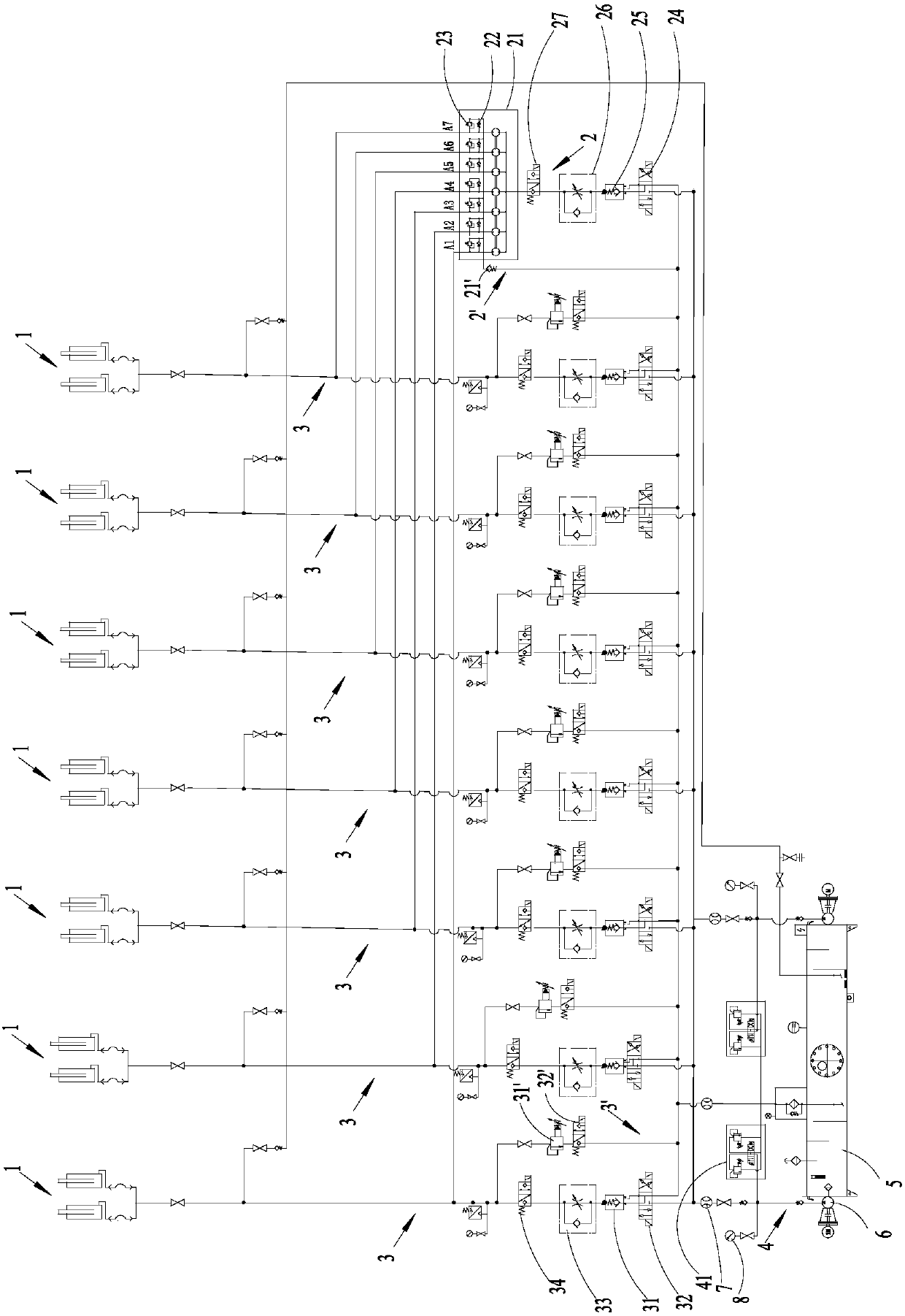
[0061] Specifically, such as figure 1 As shown, the hydraulic control system includes a plurality of hydraulic cylinders 1. Usually, one hydraulic cylinder 1 controls one hinge dam to drive the hinge dam to go up and down. Of course, in order to ensure the reliable lifting of the hinge dam, a scheme of jointly driving a hinge dam to lift by multiple hydraulic cylinders 1 can also be adopted.

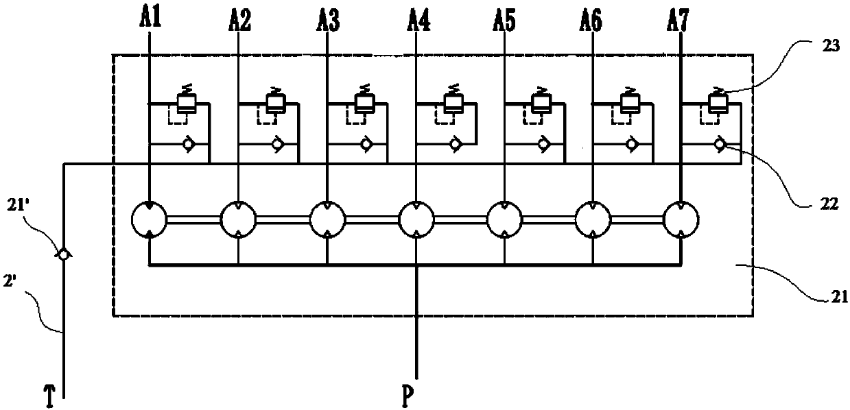
[0062] The hydraulic control system also includes a first branch 2 that controls the synchronous actions of the hydraulic cylinders 1. The first branch 2 includes a diversion s...


PUM


Abstract

The invention relates to a hydraulic control system and a hinge dam assembly. The hydraulic control system comprises a first branch circuit which comprises a flow-distributing synchronous valve. The flow-distributing synchronous valve comprises a cavity, a rotary shaft arranged in the cavity rotatably and a plurality of rotors arranged on the rotary shaft; the rotors are axially distributed in a spaced manner along the rotary shaft and rotate synchronously along with the rotary shaft, the flow-distributing synchronous valve is provided with a first opening and a plurality of second openings where media circulate and which communicate to the cavity, the second openings communicate to hydraulic cylinders one by one, and the rotors and the second openings are formed correspondingly one by one; when the rotors separately convey the media from the first opening to the second openings, the hydraulic cylinders generate first strokes; in the first strokes, the hydraulic cylinders drive hinge dams to ascend synchronously; and when the rotors convey the media from the second openings to the first opening, the hydraulic cylinders generate second strokes; and in the first strokes, the hydraulic cylinders drive hinge dams to ascend synchronously.

Description

technical field [0001] The present application relates to the technical field of movable dams, in particular to a hydraulic control system and a hinge dam assembly. Background technique [0002] Hinge dam is a new type of movable sluice. It is mainly composed of dam surface, hydraulic rod, hydraulic cylinder and hydraulic pump station. The dam surface is connected with the foundation connecting plate fixed on the foundation of the river bank. The way is to use the hydraulic cylinder to straighten the back of the dam surface with the bottom as the axis of the movable water-retaining dam, so as to realize the purpose of raising the dam to stop the water and lowering the dam to discharge the flood. [0003] Multiple hinge dams can be set in the river channel. When all the hinge dams are raised, the flow in the river channel is the largest. When only a few hinge dams are raised, the flow control in the river channel can be realized. So as to achieve the purpose of throttling. ...

Claims


Application Information

Patent Timeline
IPC IPC(8): F15B13/06F15B11/22E02B7/44
Inventor 刘旭冉陈晏育赵月芬赵建华袁俊玲宋太玉赵晓兰耿晔晗刘杰王湛
Owner CHINA INST OF WATER RESOURCES & HYDROPOWER RES
Learn More